11
5mm
7
8
9
10
Lock the arm
J
or
(A/B/C)+E/D/G
E
C2
C4
C4
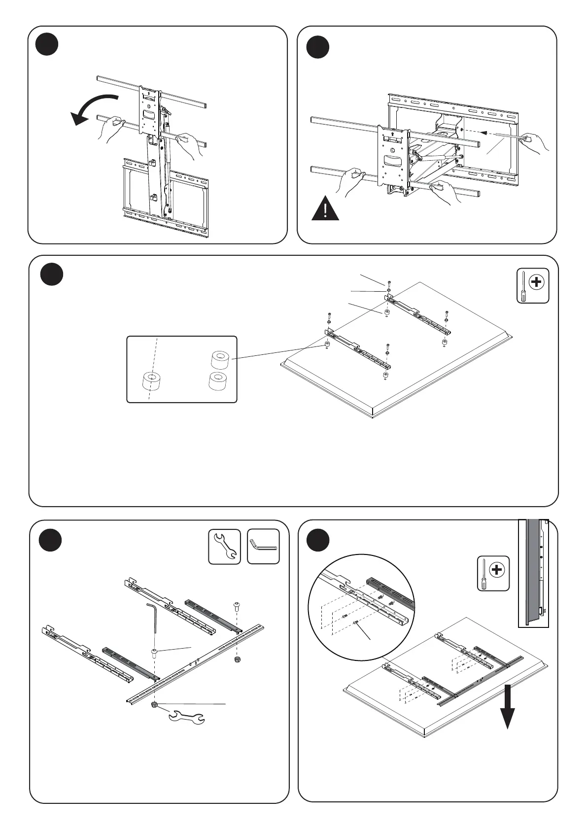
Lower the Arm
Pull the spring arm down until it is perpendicular
to the wall.
Select the appropriate size mounting bolt (Select one size #A, B or C) and washer (#E, D, or G) for your display’s mounting holes
and verify the length of the VESA bolt is not too long. If you are unsure of the correct bolt size for your display refer to your
display’s user manual or contact the display’s manufacturer for sizing information. If necessary, use the included spacers (#C2)
between the mount and the screen as shown to adjust the length of the mounting bolt. Multiple spacers can be used in
combination to achieve the desired bolt depth. Attach the VESA Arms (#DD) using the selected bolts and tighten until secure.
Do not overtighten.
Lock the Arm
Attach the VESA Arms to the TV
Assemble the Crossbar
11
Attach the Crossbar (No Soundbar)
Insert the Arm Lock Pin (#K) through the holes
shown here to lock the arm in the lowered position
for easier access to hang the TV.
Assemble the Crossbar (#EE) by attaching the Crossbar
Latches (#GG) over the bar as shown, then secure them
together using the Bolts (#C4) through both pieces into
the Nuts (#C4).
If a soundbar will not be connected to the mount attach
the crossbar at a height that it is close to the bottom of
the TV without being visible. Secure it to the VESA Arms
using the bolts (C6) and tighten them until secure.
C6