- 7 -
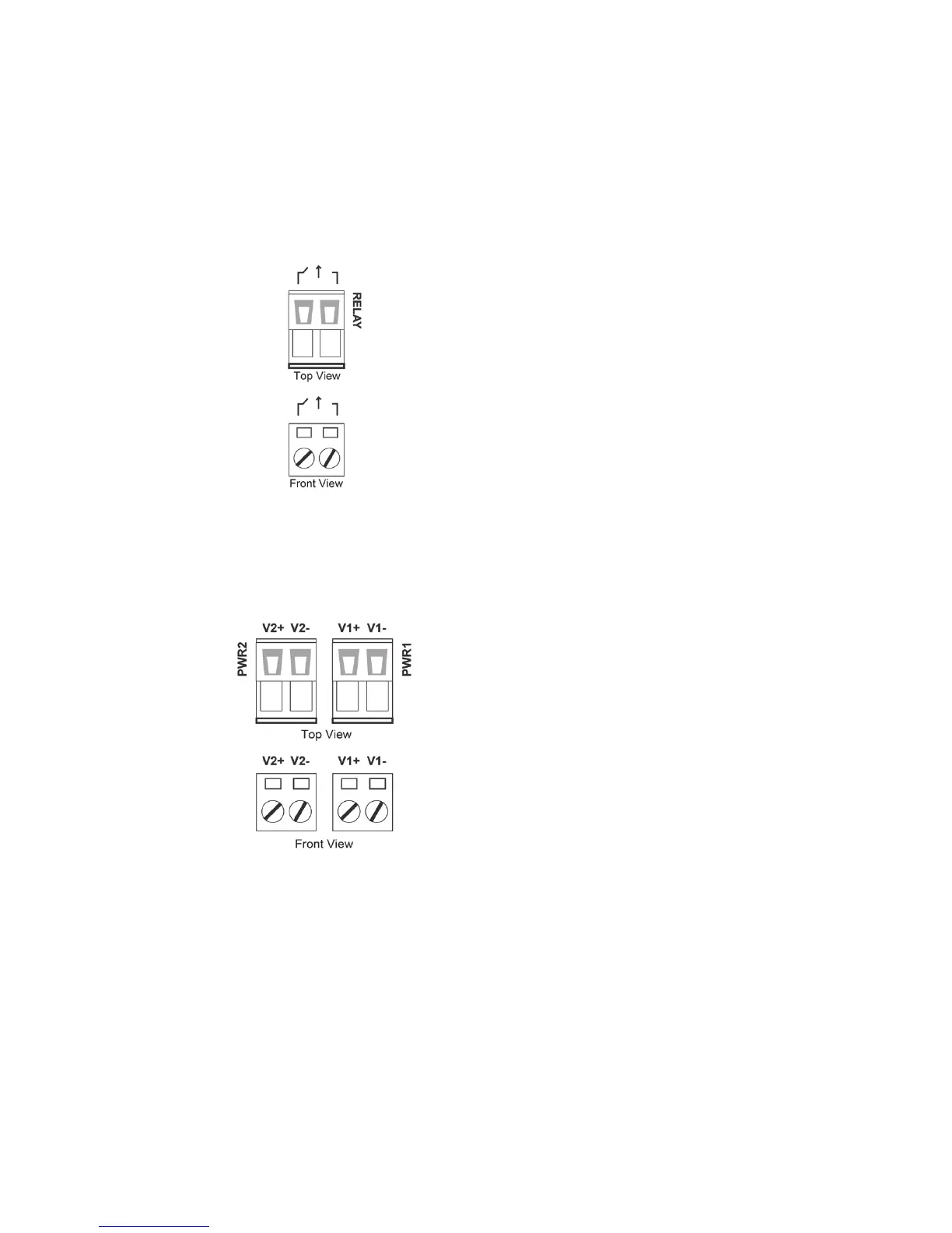
Wiring the Relay Contact
The Industrial Secure Router has one set of relay outputs. This relay
contact uses one contacts of the terminal block on the Industrial Secure
Router’s top panel. Refer to the next section for detailed instructions on
how to connect the wires to the terminal block connector, and how to
attach the terminal block connector to the terminal block receptor.
In this section, we illustrate the meaning of the contact used to connect
the relay contact.
FAULT:
The two contacts of the 2
block connector are used to detect
user
-configured events. The two wires
attached to the fault contacts form an
open circuit when a user
configured event
is triggered. If a user
does not occur, the fault circuit remains
closed.
Wiring the Redundant Power Inputs
The Industrial Secure Router has two sets of power inputs—power input 1
and power input 2. The top and front views of one of the terminal block
connectors are shown here.
STEP 1: Insert the negative/positive DC
wires into the V+/V
To keep the DC wires from pulling
front of the terminal block connector.
STEP 3: Insert the plastic terminal block
connector prongs into the terminal block
recepto
r, which is located on the Industrial
Secure Router’s top panel.
 Loading...