- 8 -
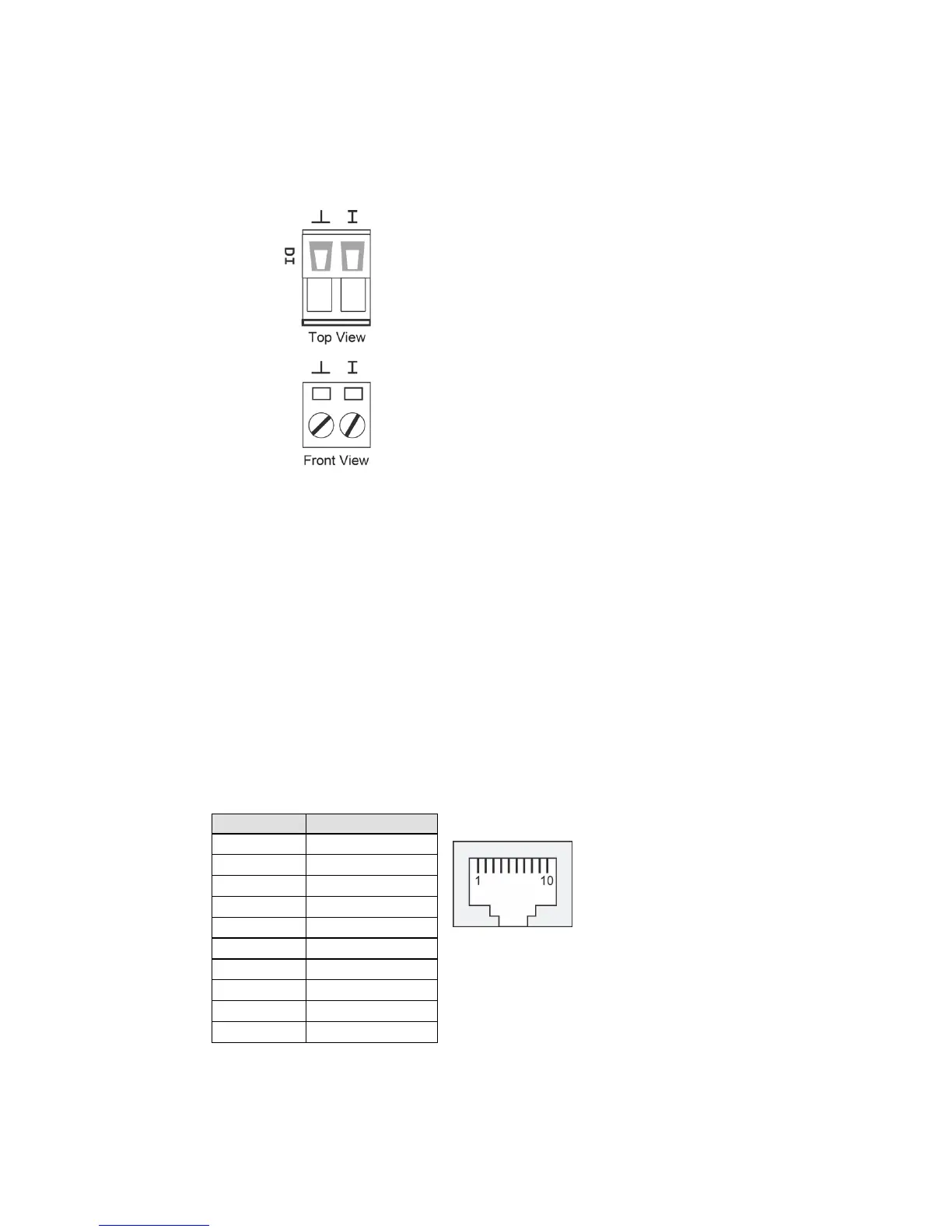
Wiring the Digital Inputs
The Industrial Secure Router has one set of digital input, DI. The DI
consists of two contacts of the 2-pin terminal block connector on the
Industrial Secure Router's top panel, which are used for the DC inputs.
The top and front views of one of the terminal block connectors are shown
here.
STEP 1: Insert the negative
(ground)/positive DI wires into the
To keep the DI wires from pulling
ront of the terminal block connector.
Insert the plastic terminal block
connector prongs into the terminal block
receptor, which is located on the Industrial
Secure Router’s top panel.
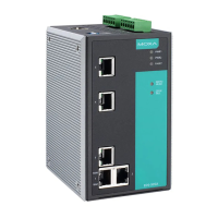
Communication Connections
Each Industrial Secure Router has three types of communication port:
• 1 RJ45 console port (RS-232 interface)
• 8 10/100BaseT(X) ports
• 2 1000BaseSFP ports
RS-232 Connection
The Industrial Secure Router has one RS-232 (10-pin RJ45) console port,
located on the top panel. Use either an RJ45-to-DB9 (see the cable
following wiring diagrams) to connect the Industrial Secure Router’s
console port to your PC’s COM port. You may then use a console terminal
program, such as Moxa PComm Terminal Emulator, to access the
Industrial Secure Router’s console configuration utility.
RJ45 (10-pin) Console Port Pinouts
 Loading...