- 11 -
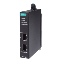
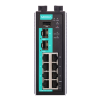
LED Indicators
The front panel of the Moxa Industrial Secure Router contains several LED
indicators. The function of each LED is described in the following table:
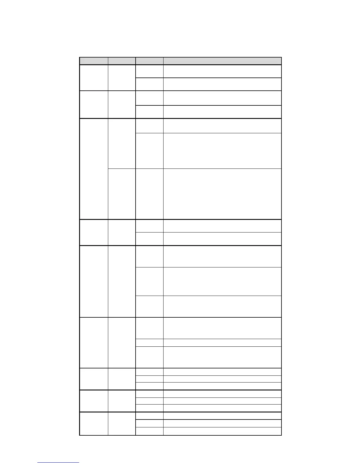
Power is being supplied to power input P1
on the main module.
Power is not being supplied to power input
P1 on the main module.
Power is being supplied to power input P2
on the main module.
Power is not being supplied to power input
P2 on the main module.
The system passed the self-diagnosis test
on boot-up and is ready to run.
• The switch is under reset progress (1
time/s)
• ABC-02-USB-T detected (1 time/s)
• Locate specific switch from MXview (2
The system failed the self-diagnosis test
on boot-up.
• RAM Test Fail/System Info Read
Fail/Switch Init./PTP PHY error Fail
(+Green MSTR/HEAD lit on: HW Fail)
• FW Checksum Fail/Uncompress Fail
(+Green CPLR/TAIL lit on: SW Fail)
When a user-configured event is
triggered.
When a user-configured event has not
been triggered.
When the EDR-810 is set as the Master of
the Turbo Ring, or as the Head of the
The EDR-810 has become the Ring Master
of the Turbo Ring, or the Head of the
Chain, after the Turbo Ring or the Turbo
When the EDR-810 is not the Master of this
Turbo Ring or is set as the Member of the
When the EDR-810 coupling function is
enabled to form a back-up path, or when
it's set as the Tail of the Turbo Chain.
When the Turbo Chain is down.
When the EDR-810 disables the coupling
function, or is set as the Member of the
TP port’s 10 Mbps link is active.
Data is being transmitted at 10 Mbps.
TP port’s 10 Mbps link is inactive.
TP port’s 100 Mbps link is active.
Data is being transmitted at 100 Mbps.
TP port’s 100 Mbps link is inactive.
SFP port’s 1000 Mbps link is active.
Data is being transmitted at 1000 Mbps.
SFP port’s 1000 Mbps link is inactive.
 Loading...