Do you have a question about the Moxa Technologies ioLogik E2200Series and is the answer not in the manual?
Lists the main capabilities and advantages of the ioLogik E2200 series, including front-end intelligence and active messaging.
Details the standard and optional items included in the ioLogik E2200 series package for users.
Provides a table detailing the specifications and operating temperatures of different ioLogik E2200 models.
A guide to help users select the appropriate ioLogik E2200 model based on I/O channel requirements.
General technical specifications covering LAN, serial communication, power, and environmental limits for the series.
Detailed input/output, isolation, and power specifications for the ioLogik E2210 model.
Detailed input/output, isolation, and power specifications for the ioLogik E2212 model.
Detailed digital I/O, relay output, and power specifications for the ioLogik E2214 model.
Detailed analog input/output, sampling rate, and power specifications for the ioLogik E2240 model.
Detailed analog/digital I/O, sampling rate, and power specifications for the ioLogik E2242 model.
Detailed RTD input, digital output, and power specifications for the ioLogik E2260 model.
Detailed thermocouple input, digital output, and power specifications for the ioLogik E2262 model.
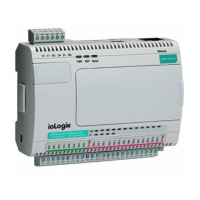
Illustrations and dimensions of the ioLogik E2200 series devices with and without an LCM.
Identifies hardware components, panel layout, pin assignments, and LED indicators on the device.
Instructions for physically installing the ioLogik E2200, including power connection and grounding.
Steps for downloading and installing the ioAdmin configuration utility from Moxa's website.
Describes three methods to reset the ioLogik E2200 to its default factory settings.
Guides on configuring the host PC's IP and establishing an Ethernet connection to the ioLogik device.
Explains how to expand I/O capabilities by connecting additional ioLogik R2140 units via RS-485.
Information on configuring the RS-485 port baudrate using the physical dial on the device.
Visual diagrams illustrating how to connect various types of digital and analog I/O signals to the device.
Instructions on backing up and restoring device configurations using the ioAdmin utility.
Outlines the necessary hardware and software requirements for running the ioAdmin utility.
Describes capabilities like remote management, configuration file handling, and device management lists.
Provides an overview of the ioAdmin main screen layout, including title, menu bar, and navigation panel.
Details functions accessible only when logged in as administrator, covering various configuration tabs.
Guide to configuring individual I/O channels, including digital, analog, RTD, and TC inputs/outputs.
Explains how to set server parameters like password, name, location, and time synchronization.
Covers network settings including IP, DNS, serial communication, and web access configurations.
Instructions on how to update the ioLogik's firmware using the ioAdmin utility.
Configuration for the Host Connection Watchdog to monitor network connectivity and activate safe status.
Details how to configure local logic rules and event-driven automation using the Click&Go feature.
Configuration for creating and managing active tags for communication with OPC servers.
Configuration of SNMP V1, V2c, and V3 for network monitoring and device management.
How to view TCP/UDP active messages and monitor system events in the ioAdmin interface.
Guide to installing and using ioEventLog utility for monitoring status events on the network.
Explains the Click&Go logic concept and its benefits for event-driven automation and remote I/O control.
Introduces the Click&Go Logic panel and its components for creating and managing rulesets.
Explains how rules are the fundamental building blocks for defining trigger conditions and actions.
Details how to configure DI, DO, and AI channels for use within Click&Go logic rules.
How to set DI channels to operate in Digital Input or Event Counter modes with filtering options.
How to set DO channels to operate in Digital Output or Pulse Output modes with pulse parameters.
How to configure AI channels for voltage or current input, including auto-scaling and range settings.
How to assign custom names (aliases) to I/O channels for easier identification in programming.
Procedures for testing the functionality of configured I/O channels within the ioAdmin interface.
How to configure global variables like internal registers, timers, and servers for Click&Go rules.
Configuration of internal registers used as flags or for logic redirection in Click&Go rules.
Configuration of timers for delaying, triggering, or repeating actions within Click&Go logic.
Setting up SNMP trap servers for monitoring network and I/O status updates.
Configuring email server parameters and recipient lists for sending alerts via Click&Go.
Setting up message servers for sending event messages via TCP/UDP packets.
Details how to specify conditions for triggering THEN/ELSE actions in Click&Go rules.
Describes the available actions that can be performed based on IF conditions being met or not met.
Steps to upload, restart, and run the configured Click&Go rule-set for device operation.
Explains how to access and navigate the ioLogik's web-based configuration interface via a browser.
Displays basic information about the ioLogik server, including model, firmware, and IP address.
Settings for system time and time server synchronization through the web console.
Setting server name, location, and enabling communication watchdog functionality.
Configuring static or dynamic IP addresses, subnet mask, and gateway for network connectivity.
Viewing DI channel status and configuring DI or Event Counter modes via the web console.
Viewing DO channel status and configuring DO or Pulse Output modes via the web console.
Viewing AI channel status and configuring input modes and auto-scaling via the web console.
Configuring analog output channels with power-on and safe status settings via the web console.
Viewing RTD channel status and configuring sensor types and input modes via the web console.
Viewing TC channel status and configuring sensor types and input modes via the web console.
Controlling network access by specifying allowed IP addresses or ranges for the ioLogik.
Enabling and configuring SNMP V1, V2c, and V3 for network monitoring and device management.
Updating the ioLogik's firmware through the web console interface.
Importing saved system configurations from a file into the ioLogik.
Exporting the current system configuration for backup or duplication to another ioLogik.
Changing the device's administrator password to enhance security.
Resetting the ioLogik to its original factory default settings, losing all current configurations.
Saving configuration changes and restarting the device to apply them.
Explains Moxa Active OPC Server's role as an OPC driver for HMI/SCADA systems.
Contrasts traditional 'pull' polling with Moxa's 'push' based active reporting for I/O data.
Highlights key features like automatic tag generation and faster, more accurate data collection.
Provides instructions for downloading and installing the Active OPC Server software.
Step-by-step guide on configuring and creating active tags for Active OPC Server Lite using ioAdmin.
Setting the heartbeat interval to monitor the connection status between ioLogik and Active OPC Server.
Explains read-only vs. read/write access for tags, noting output channels and Click&Go logic impact.
Explains how to navigate and operate the Liquid Crystal Display Module using its buttons.
Details the information and settings accessible through different submenus on the LCM display.
A table listing network ports used by the ioLogik E2200 for various communication protocols.
Lists the default IP address, Netmask, Gateway, and communication settings for the ioLogik E2200.
Wiring diagram for connecting analog input sensors to the ioLogik.
Wiring diagram for connecting analog output devices to the ioLogik.
Wiring example for connecting dry contact digital input sensors.
Wiring examples for NPN and PNP type sensors for digital input wet contact.
Diagrams illustrating the wiring for 2-wire and 3-wire RTD sensors.
Diagram showing the structure and 2-wire connection for thermocouple sensors.
Pinout details for the input and output terminals of the ioLogik E2210.
Pinout details for the input and output terminals of the ioLogik E2212.
Pinout details for the input and output terminals of the ioLogik E2214.
Pinout details for the input and output terminals of the ioLogik E2240.
Pinout details for the input and output terminals of the ioLogik E2242.
Pinout details for the input and output terminals of the ioLogik E2260.
Pinout details for the input and output terminals of the ioLogik E2262.
| Model | ioLogik E2200 Series |
|---|---|
| Operating Temperature | -40 to 75°C (-40 to 167°F) |
| Input Channels | Varies by model |
| Output Channels | Varies by model |
| Digital Input Channels | Varies by model |
| Digital Output Channels | Varies by model |
| Ethernet Ports | 2 x 10/100 Mbps |
| Communication Protocols | SNMP |
| Power Supply | 12 to 48 VDC |
| Mounting | DIN-rail |
| Certifications | CE, FCC, UL |