Do you have a question about the Moxa Technologies IMC-21GA-T and is the answer not in the manual?
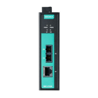
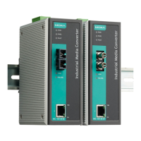
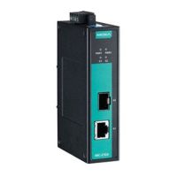
The IMC-21GA series comprises industrial 10/100/1000BaseT(X) to 100/1000BaseFX media converters, offering a cost-effective solution specifically engineered for reliable and stable operation in demanding industrial environments.
The IMC-21GA serves as a media converter, bridging the gap between copper-based Ethernet networks (10/100/1000BaseT(X)) and fiber optic networks (100/1000BaseFX). This conversion allows for extended network distances and enhanced immunity to electromagnetic interference, which are crucial in industrial settings. The device supports both multi-mode (0.5 km) and single-mode (10 km) fiber connections, utilizing SC fiber connectors. For Gigabit Ethernet fiber ports, the IMC-21GA requires Gigabit mini-GBIC fiber transceivers to function correctly. The concept behind both LC and SC fiber ports and cables is straightforward: optical signals do not require a circuit for data transmission. Instead, one optical line transmits data from device I to device II, and the other optical line transmits data from device II to device I, enabling full-duplex transmission. When connecting devices, it's essential to connect the transmit (Tx) port of device I to the receive (Rx) port of device II, and the Rx port of device I to the Tx port of device II. If custom cables are made, labeling the two sides of the same line (e.g., A-to-A and B-to-B) is recommended.
The IMC-21GA features a 10/100/1000BaseT(X) Ethernet port on its front panel for connecting to Ethernet-enabled devices. This port supports auto-negotiation for transmission speeds of 10 Mbps, 100 Mbps, and 1000 Mbps, adhering to the IEEE 802.3u standard. Auto-negotiation occurs when an RJ45 cable connection is established and each time a LINK is enabled. The IMC-21GA advertises its capabilities for these speeds, expecting the connected device to do the same. This ensures that the devices agree to operate at a compatible speed. If connected to a non-negotiating device, the RJ45 Ethernet port will default to 10 Mbps speed and half-duplex mode, as per the IEEE 802.3u standard.
A key feature of the IMC-21GA is its Link Fault Pass-Through (LFP) capability, which can be enabled or disabled via a DIP switch. When LFP is enabled, the link status on the TX port will inform the FX port of the same device, and vice versa. This ensures that if a link fault occurs on one side of the converter, the fault is propagated to the other side, allowing connected devices to react appropriately (e.g., by initiating a backup path). The fiber port's connection speed (100 Mbps or 1000 Mbps) is also DIP switch selectable, providing flexibility for different network requirements. When setting the fiber speed, it's important to use the appropriate Moxa SFP modules: SFP-1FE Series for 100 Mbps and SFP-1G Series for 1000 Mbps.
The device also supports Energy Efficient Ethernet (EEE) as defined by IEEE 802.3az, which can be enabled or disabled via a DIP switch. When EEE is enabled, the device can reduce power consumption during periods of low data activity, contributing to energy savings.
The IMC-21GA is designed for ease of use and robust operation. It is DIN rail mountable, allowing for convenient installation in industrial control cabinets. The aluminum DIN rail attachment plate is pre-fixed to the back panel. If reattaching, ensure the stiff metal spring is positioned towards the top.
The device incorporates redundant power inputs, allowing both power inputs to be connected simultaneously to live DC power sources. In the event of one power source failing, the other live source automatically acts as a backup, ensuring continuous operation of the IMC-21GA. The power inputs are connected via a 4-contact terminal block connector on the top panel. Wiring involves inserting negative/positive DC wires into the V-/V+ terminals, tightening wire-clamp screws with a flat-blade screwdriver, and then inserting the plastic terminal block connector prongs into the receptor.
The Auto MDI/MDI-X function simplifies connections to Ethernet devices. This feature allows users to connect the IMC-21GA's 10/100/1000BaseT(X) ports to any type of Ethernet device using either a straight-through or cross-over Ethernet cable, eliminating the need for specialized cables.
LED indicators on the front panel provide clear status information. PWR1 and PWR2 LEDs indicate whether power is being supplied to the respective power inputs (V1+, V1- and V2+, V2-). The G1 LED indicates the status of the Gigabit Copper (TP) port, showing if the 1000 Mbps link is active (On, Green), data is being transmitted at 1000 Mbps (Blinking, Green), the 1000 Mbps link is inactive (Off, Green), the 10/100 Mbps link is active (On, Amber), data is being transmitted at 10/100 Mbps (Blinking, Amber), or the 10/100 Mbps link is inactive (Off, Amber). Similarly, the G2 LED indicates the status of the Fiber port, showing if the 1000 Mbps link is active (On, Green), data is being transmitted at 1000 Mbps (Blinking, Green), the 1000 Mbps link is inactive (Off, Green), the 100 Mbps link is active (On, Amber), data is being transmitted at 100 Mbps (Blinking, Amber), or the 100 Mbps link is inactive (Off, Amber).
For maintenance and installation, several safety precautions are highlighted. Before installing or wiring the IMC-21GA, it is crucial to disconnect the power cord. When wiring, calculate the maximum possible current in each power wire and common wire, adhering to all electrical codes to prevent overheating and potential damage to the equipment.
Proper grounding of the IMC-21GA is essential to limit the effects of noise due to electromagnetic interference (EMI). The ground connection should be run from the ground screw to a well-grounded mounting surface, such as a metal panel, before connecting other devices.
Careful wiring practices are recommended to minimize interference. Signal or communications wiring and power wiring should not be run in the same conduit. Wires with different signal characteristics should be routed separately. The general rule is to bundle wiring that shares similar electrical characteristics. Input and output wiring should also be kept separate. It is strongly advised to label all wiring to devices in the system for easier identification and troubleshooting. If power wiring and device wiring paths must cross, ensure the wires are perpendicular at the intersection point.
The DIP switches on the device allow for configuration changes, such as fiber speed, Energy Efficient Ethernet, and Link Fault Pass-Through. After changing any DIP switch setting, the IMC-21GA must be powered off and then powered back on for the new settings to take effect.
The IMC-21GA is designed with an IP30 protected metal case, offering a degree of protection against solid objects, which contributes to its durability in industrial environments. It also supports a wide operating temperature range, with standard models operating from -10 to 60°C and wide temperature models from -40 to 75°C, making it suitable for diverse industrial applications.
| Operating Temperature | -40 to 75°C (-40 to 167°F) |
|---|---|
| Storage Temperature | -40 to 85°C (-40 to 185°F) |
| Humidity | 5 to 95% (non-condensing) |
| Standards | IEEE 802.3, IEEE 802.3u, IEEE 802.3ab, IEEE 802.3z |
| Media Type | 10/100/1000Base-T(X) to 1000Base-SX/LX |
| Ports | 1 x 10/100/1000Base-T(X), 1 x 1000Base-SX/LX |
| Fiber Port | 1000Base-SX/LX |
| Power Supply | 12 to 48 VDC |
| Housing | IP30 |
| Certifications | CE, FCC, UL |
| RJ45 Port | 10/100/1000BaseT(X) auto negotiation speed, Full/Half duplex mode, and auto MDI/MDI-X connection |