– 1 – – 2 – – 3 –
P/N: 1802054000312
NPort 5100 Series
Quick Installation Guide
Third Edition, January 2011
1. Overview
NPort 5100 series device servers are compact, palm-sized data
communication devices that allow you to control RS-232 (NPort
5110), RS-422/485 (NPort 5130), and RS-232/422/485 (NPort
5150) serial devices over a TCP/IP-based Ethernet.
Note: “-T” indicates an extended temperature model.
2. Package Checklist
Before installing the NPort 5100 series device server, verify that
the package contains the following items:
• 1 NPort 5100 series 1-port serial device server
• 4 stick-on pads
• Documentation and software CD
• Quick Installation Guide
• Warranty card
Optional Accessory
• DK-35A: DIN-Rail Mounting Kit (35 mm)
Notify your sales representative if any of the above items are missing or
damaged.
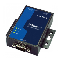
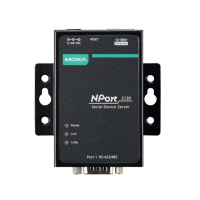
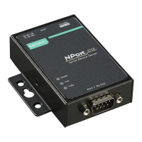
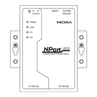
3. Hardware Introduction
As shown in the following figures, NPort 5100 series device servers
have one male DB9 port for transmitting RS-232 (NPort 5110),
RS-422/485 (NPort 5130), or RS-232/422/485 (NPort 5150) serial
data.
The NPort 5110, NPort 5130, and NPort 5150 have the
same form factor.
Reset Button—Press the Reset button continuously for 5 sec to
load factory defaults: Use a pointed object, such as a straightened
paper clip or toothpick, to press the reset button. This will cause
the Ready LED to blink on and off. The factory defaults will be
loaded once the Ready LED stops blinking (after about 5 seconds).
At this point, you should release the reset button.
LED Indicators—NPort 5100’s top panel has three LED indicators,
which are described in the following table.
Ready Red Steady on: Power is on and NPort is
booting up.
Blinking: Indicates an IP conflict, or
DHCP or BOOTP server is not responding
Green Steady on: Power is on and NPort is
functioning normally.
Blinking: The NPort has been located
by NPort Administrator’s Location function
Power is off, or power error condition
exists.
10 Mbps Ethernet connection.
100 Mbps Ethernet connection.
Off Ethernet cable is disconnected, or has a
Serial port is receiving data.
Serial port is transmitting data.
No data is being transmitted or received
through the serial port.
Adjustable pull high/low resistor for RS-422/485
(150 KΩ or 1 KΩ)
Jumpers are used to set the
pull high/low resistor values.
The default is 150 KΩ. Short
the jumpers to set this value to
1 KΩ. Do not use the KΩ
setting with RS-232 mode,
since doing so will degrade the
RS-232 signals and shorten
the communication distance.
4. Hardware Installation Information
STEP 1: After removing the NPort 5100 series device server from
the box, connect the NPort 5100 series device server to a network.
Use a standard straight-through Ethernet cable to connect to a hub
or switch. When setting up or testing the NPort 5100 series device
server, you might find it convenient to connect directly to your
computer’s Ethernet port. In this case, use a cross-over Ethernet
cable.
STEP 2: Connect the NPort 5100 series device server’s serial port
to a serial device.
STEP 3: Connect the power adaptor.
STEP 4: Placement options
In addition to placing
the NPort 5100 on a
desktop or other
horizontal surface,
you may also make
use of the DIN-
Wall Mount options,
as illustrated here.
5. Software Installation Information
To install NPort Administration Suite, insert the NPort
Document & Software CD into your computer’s CD-ROM drive.
Once the NPort Installation CD window opens, click on the
Installation button, and then follow the instructions on the
screen.