Outdoor Unit Disassembly 39
PCB board 6
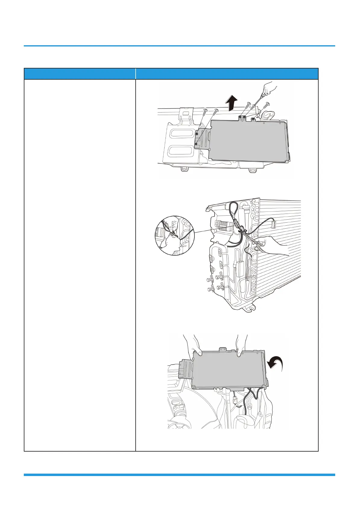
Procedure Illustration
1) Remove 5 screws of the cover of
electrical control box cover and
remove it. (see CJ_ODU_Multi_
PCB_006-1).
2) Cut the ribbon by a shear and
disconnect the 4-way valve
connector. (see CJ_ODU_Multi_
PCB_006-2).
3) Ture over the electronic control box
subassembly. (see CJ_ODU_Multi_
PCB_006-3).
CJ_ODU_Multi_PCB_006-1
CJ_ODU_Multi_PCB_006-2
CJ_ODU_Multi_PCB_006-3
Note: This section is for reference only. Actual unit appearance may vary.