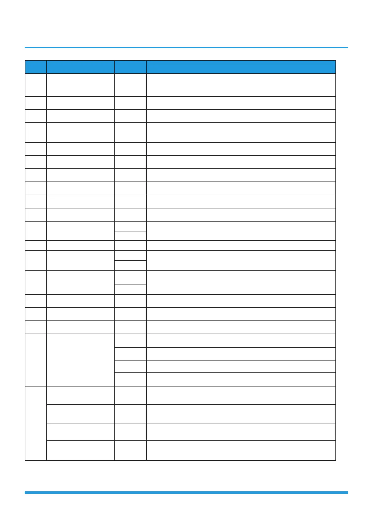
No. Name CN# Meaning
1 T3/T4 CN17
T3: condenser temperature sensor
T4: outdoor ambient temperature sensor
2 CN7 CN7 connect to discharge sensor
3 Test Port CN26 connect to DR board CN1
4 LOW/HIGH CN14
Red: low pressure protect
Yellow: high pressure protect
5 Comp Top CN12 compressor top temperature sensor
6 L-OUT L-OUT connect to IPM board CN4
7 N-OUT N-OUT connect to IPM board CN5
8 CN32 CN32 connect to DR board CN5
9 CN33 CN33 connect to DR board CN5
10 N-in CN4 N_in: connect to N-line (208-230V AC input)
11 HEAT2
CN8
connect to chassis heater, 208-230V AC when is ON
CN9
12 L-in CN3 L_in: connect to L-line (208-230V AC input)
13 HEAT1
CN5
connect to compressor heater, 208-230V AC when is ON
CN6
14 4-way
CN1
connect to 4 way valve, 208-230V AC when is ON.
CN2
15 Fan-C CN13 connect to fan capacitor
16 Outdoor AC Fan CN11 connect to outdoor AC fan
17 Fan-C CN10 connect to fan capacitor
18
Electronic Expansion
valve
CN18 connect to Electric Expansion Valve A
CN19 connect to Electric Expansion Valve B
CN22 connect to Electric Expansion Valve C
CN24 connect to Electric Expansion Valve D
19
S-A CN25
Current loop communication A, signal wire, connect to the terminal
(24V DC Pulse wave)
S-B CN23
Current loop communication B, signal wire, connect to the terminal
(24V DC Pulse wave)
S-C CN20
Current loop communication C, signal wire, connect to the terminal
(24V DC Pulse wave)
S-D CN16
Current loop communication D, signal wire, connect to the terminal
(24V DC Pulse wave)
Note: This section is for reference only. Please take practicality as standard.