Outdoor Unit Disassembly 28
Procedure Illustration
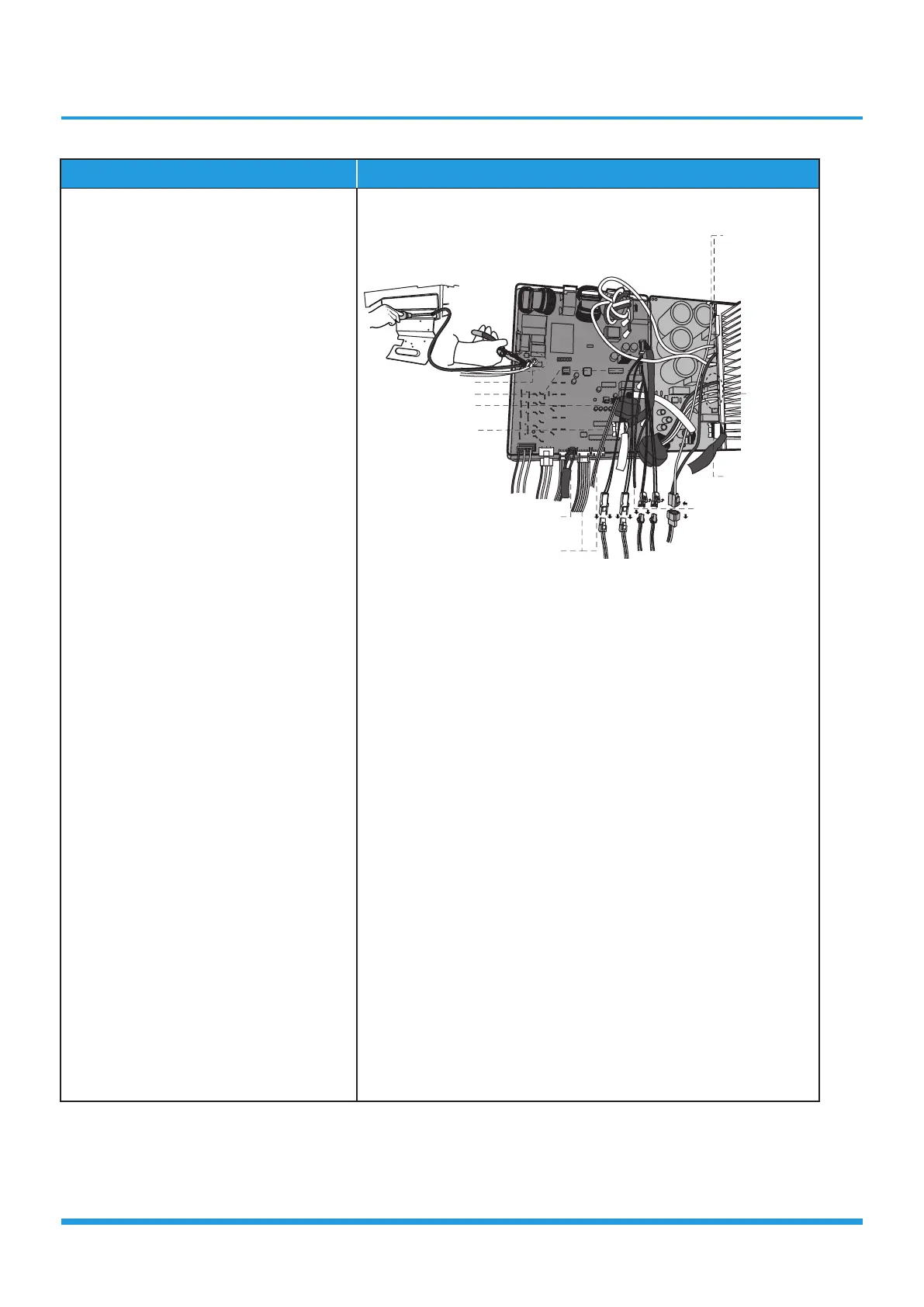
3) Disconnect the connector for outdoor
DC fan from the electronic control
board (see CJ_Multi-PCB_001-3).
4) Remove the connector for the
compressor (see CJ_Multi-
PCB_001-3).
5) Pull out the two blue wires connected
with the four way valve (see CJ_Multi-
PCB_001-3).
6) Pull out connectors of the condenser
coil temp. sensor(T3),outdoor ambient
temp. sensor(T4) and discharge temp.
sensor(TP) (see CJ_Multi-PCB_001-3).
7) Disconnect the electronic expansion
valve wire (see CJ_Multi-PCB_001-3).
8) Disconnect the communication
wire indoor PCB (see CJ_Multi-
PCB_001-3).
9) Disconnect the PFC inductor (see
CJ_Multi-PCB_001-3).
10) Then remove the electronic control box
(see CJ_Multi-PCB_001-3).
:6
6U]KX=OXK
)USS[TOIGZOUT=OXK=OZN/TJUUX6)(
+RKIZXOI+^VGTYO\K<GR\K
=G_<GR\K
*),GT
)USVXKYYUX
6,)/TJ[IZUX
::
'),GT
CJ_Multi-PCB_001-3
Note: This section is for reference only. Actual unit appearance may vary.