Page 6
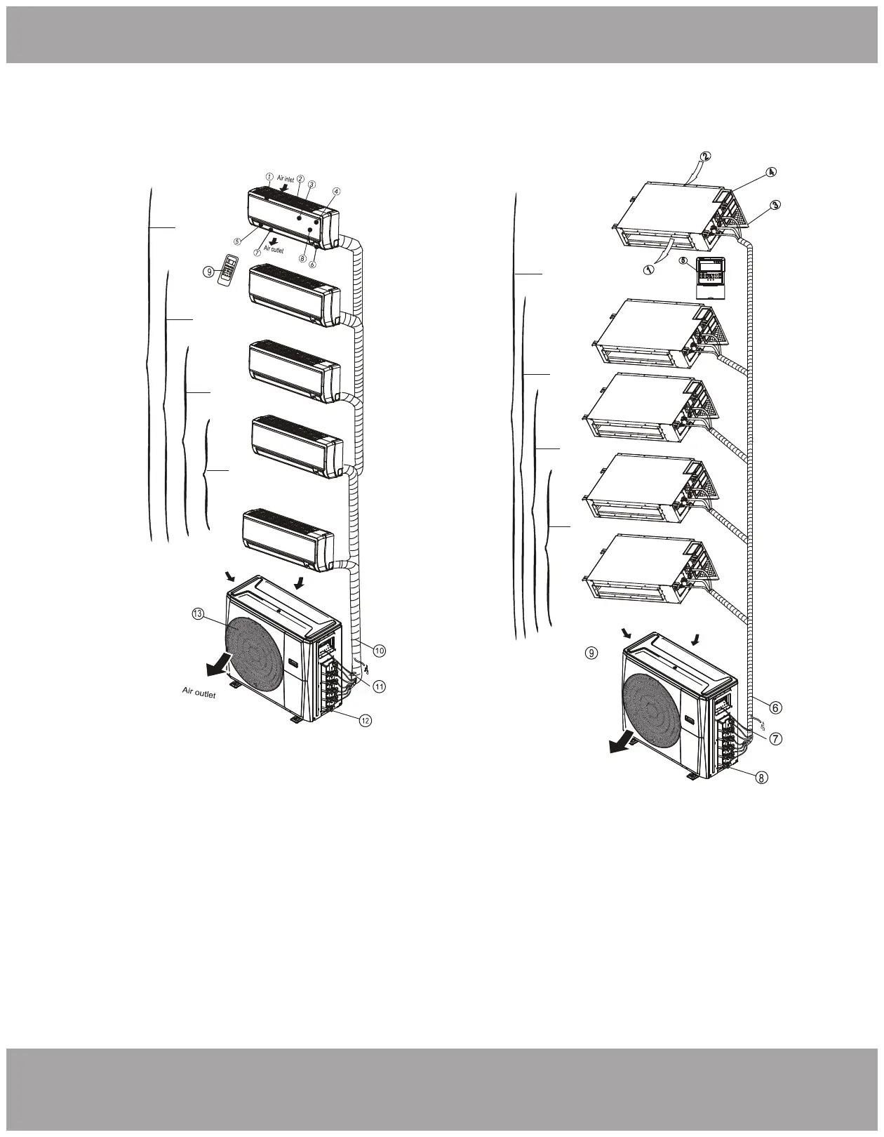
Overview - Multi-Zone
mrcool.com
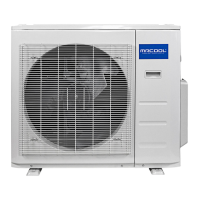
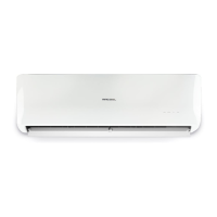
Fig. 2.1
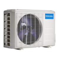
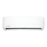
Fig. 2.2
Indoor unit
1. Panel frame
2. Rear air intake grille
3. Front panel
4. Air Purifying filter & Air filter (behind)
5. Horizontal louver
6. LCD display window
7. Vertical louver
8. Manual control button (behind)
9. Remote control holder
Outdoor unit
10. Drain hose, refrigerant connecting pipe
11. Connective cable
12. Stop valve
13. Fan hood
Indoor unit
1. Air outlet
2. Air inlet
3. Air filter
4. Electric control cabinet
5. Wire controller
Outdoor unit
6. Drain hose, refrigerant connecting pipe
7. Connective cable
8. Stop valve
9. Fan hood
5-Zone
4-Zone
3-Zone
2-Zone
5-Zone
4-Zone
3-Zone
2-Zone
Wall-Mounted Handlers Ceiling Ducted Handlers