Installation Method
Page 5 mrcool.com
2
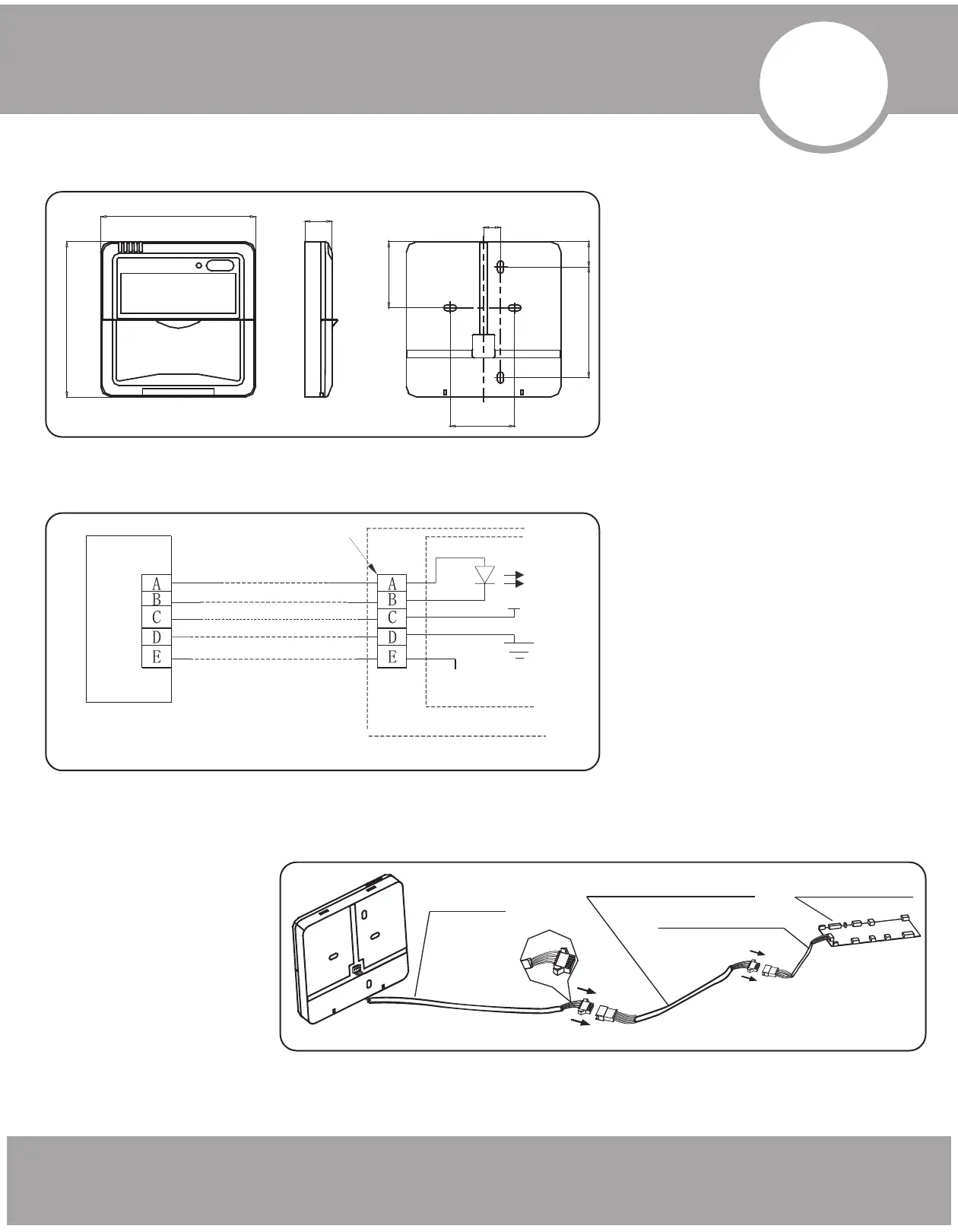
1. Wired Remote Control Structure Size Figure
2. Wiring Principle Sketch
3. Wiring Figure
Fig. 2-1
Fig. 2-2
120
120
21
51.1
13.1
19.5
85.5
50
5-Core Shield Cable, the length
is decided by installation
Wire Joint, 5p
Infrared Pipe
Indoor Unit
RUN
GND
+5V
Indoor Unit Switch Board
Wire Controller
Fig 2-3
Indoor display board
5-core wire
The connective wires group
5-core or 4-core wire
• Connect the female joint of
wires group from the
mainboard with the male
joint of connective wires
group. (See Fig.2-3)
• Please connect the other
side of connective wires
group with the male joint of
wires group leads from wire
controller. (See Fig.2-3)