Installation Method
Page 7 mrcool.com
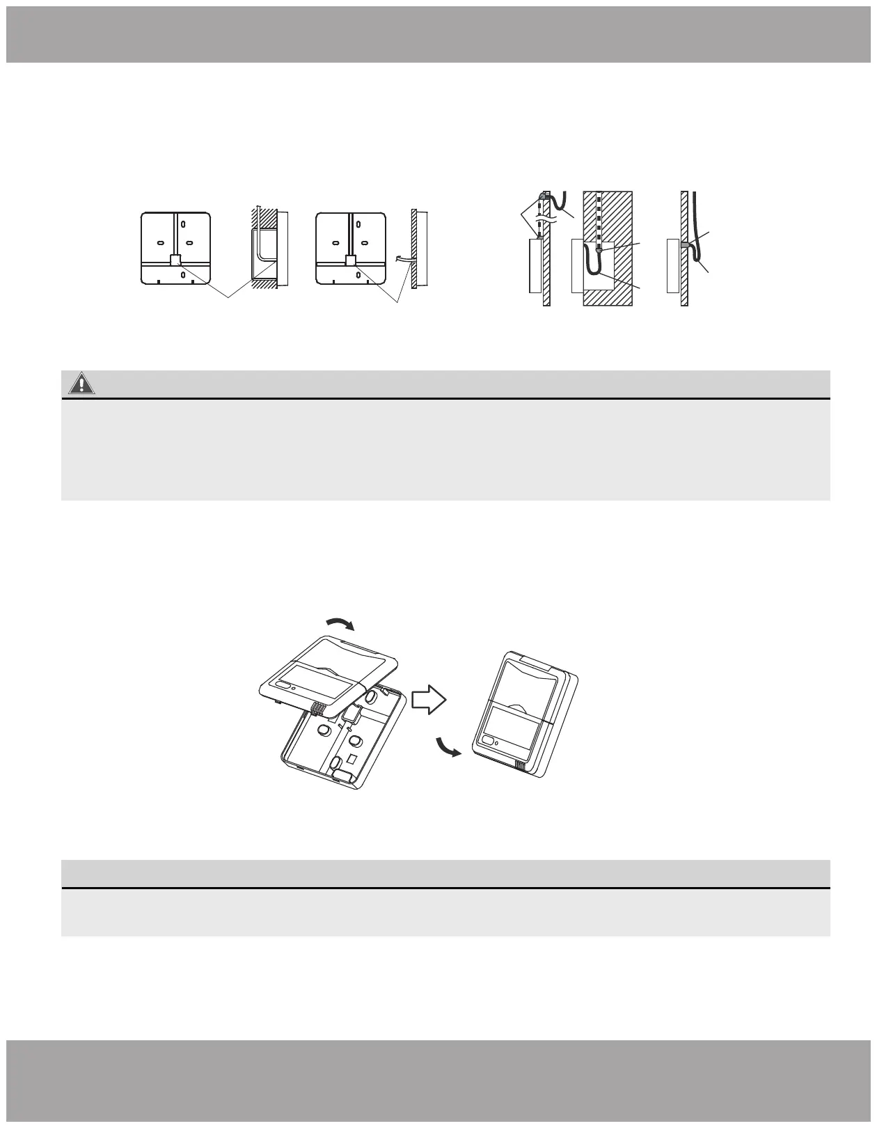
6. Wiring Continued
7. Reattach The Upper Part Of The Wire Controller
Fig 2-8
Fig 2-9
Diameter of wall hole: 2 0mm
Embedded switch
box wiring
Shielded Wiring
Wiring
hole
Wiring through the wall
Wall hole and wiring hole
Putty
Putty
Putty
Trap
Trap
Trap
WARNING
• Avoid water entering into the wired remote controller, use trap and putty to seal the connectors of
wires during wiring installation. (Fig.2-9)
• During installation, reserve a portion of the connecting wire for later convenience when taking down
the wired remote controller during maintenance procedures.
Fig 2-10
• After adjusting the upper case, buckle the upper case. Be sure to avoid clamping the wiring
during installation. (
Fig 2-1
0)
NOTE
• All the pictures in this manual are for explanation purposes only. Your wire controller may vary.