Page 23
mrcool.com
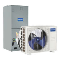
Unit Installation
Indoor Unit Model Power Supply
Max. Overcurrent
Protection (A)
208/230V (60 Hz)
15 amps4 amps
MDUI18024E/MDUI18036E
Min. Circuit
Ampacity
Electrical Connection
Electrical Parameters
208/230V (60 Hz)
15 amps
8 amps
MDUI18048E/MDUI18060E
1. The fuse is located on the main board.
2. Install a circuit breaker at every power terminal near the units (indoor unit and thermostat) with at least
0.12 in (3 mm) contact gap. Both units must reach the plug.
3. Circuit breaker and power cord specifications listed in the above table are determined based on the
maximum power input of the units.
4. Specifications of power cords listed in the above table are applicable in a working condition where ambient
temperature is 104°F (40°C) and multi-core copper cable (e.g. YJV copper cable, with insulated PE and PVC
sheath) is protected by a conduit, and is resistant to 194°F (90°C) in maximum (see IEC 60364-5-52). If
working conditions change, please adjust the specifications according to national standards.
5. Specifications of circuit breaker are based on a working condition where the working temperature is 104°F
(40°C). If working conditions change, please adjust the specifications according to national standards.
6. Use 18 AWG 6 strand thermostat wire as the connection between the indoor unit and the thermostat. The
maximum connection length is 98 feet (30 m). Please select a proper length according to local conditions.
Thermostat wire must not be twisted together.
7. The gauge of thermostat wire between the indoor unit and thermostat should be no less than 18 AWG and
at least 6 strand to ensure a proper connection.
Connecting the Power Cord & Communication Wire
WARNING
1. Before work begins, please check to ensure the unit and thermostat are powered OFF.
2. Match the terminal numbers and wire colors with the colors indicated in the indoor unit.
3. Wrong wire connection may burn the electrical components.
4. Connect the wires firmly to the wiring box. Incomplete installation may lead to a fire hazard.
5. Please use wire clamps to secure the external covers of connecting wires. (Insulators must be
clamped securely; otherwise, electrical leakage may occur.)
6. Ground wire should be connected.
7. High and low voltage wires should be led through different rubber rings of the electric box cover.
8. DO NOT bundle the thermostat wires or lay them side by side, otherwise errors will occur.
9. High and low voltage wires should be secured separately. Secure the high voltage wires with large
clamps and the low voltage wires with small clamps.
10. Use screws to tighten the thermostat wires and power cords of the unit on the terminal board.
Improper connection could create a fire hazard.
11. If the power cords and thermostat wires are not correctly connected, the air conditioner could suffer
damage.
12. Ground the system by connecting the ground wire.
13. The units should comply with all applicable local and national rules and regulations on power
consumption.
14. When connecting the power cord, make sure the phase sequence of the power supply matches with
the corresponding terminals, otherwise the compressor will be reversed and operate abnormally.