Functional Safety Installation
ULTIMA X5000 Gas Monitor Safety Manual 9
US
4.4. Proof Test Steps
1. Bypass the safety function and take appropriate action to avoid a false trip.
2. Use HART communications to retrieve any diagnostics and take appropriate action.
3. Send a HART command to the transmitter to set gas reading to the HIGH alarm setting and verify that
the analog current reaches the appropriate value.
4. Send a HART command the transmitter to set gas reading to the LOW alarm setting and verify that the
analog current reaches the appropriate value.
5. Inspect the transmitter for any visible damage or any other communication.
6. Perform sensor calibration per the instructions provided in user manual 10177361.
7. Remove any safety function bypass and restore normal operation.
4.5. Safety-relevant Parameters
The X5000 has been subjected to rigorous reliability and functional safety assessments which have
culminated in the device being certified to IEC 61508 (Ed. 2). It is assumed that the field devices will be
installed in a Safety Instrumented System (SIS) in a Low Demand or High Demand environment per
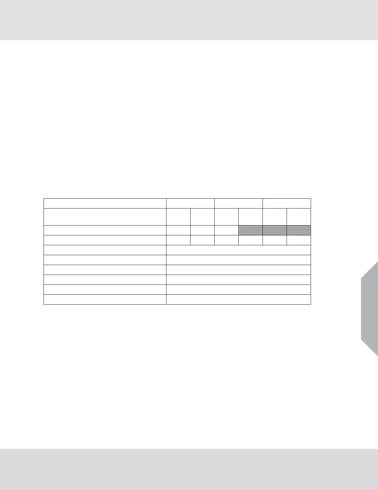
IEC 61508. The following provides the SIL parameters for the Transmitter and Receiver devices:
Safety Integrity Level (SIL)
SIL 1 SIL 2 SIL 3
Low Demand Mode (LDM) / High Demand
Mode (HDM)
LDM HDM LDM HDM LDM HDM
Structure 1oo1
X X X
Structure 1oo2
X X X X X X
λSD, λSU, λDD, λDU
See Table 1
Hardware Fault Tolerance (HFT)
SIL 2 HFT = 0, SIL 3 HFT = 1
Type Classification
B
Mean Time to Restoration (MTTR)
4 hours
Proof Test Interval (PTI)
3 months
Systematic Capability
SC 2
4.6. Application specific restrictions
The following application specific restrictions are applicable to the X5000 and have been considered during
the Failure Modes, Effects and Diagnostic Analysis of the X5000. These restrictions shall be included in the
safety manual for the X5000.
The failure rates for the Xcell sensor sections do not include the sensor failure rates, which must be
added to obtain the complete metrics.
If the relay board option is used the Fault Relay output must be monitored by the logic solver.
 Loading...


