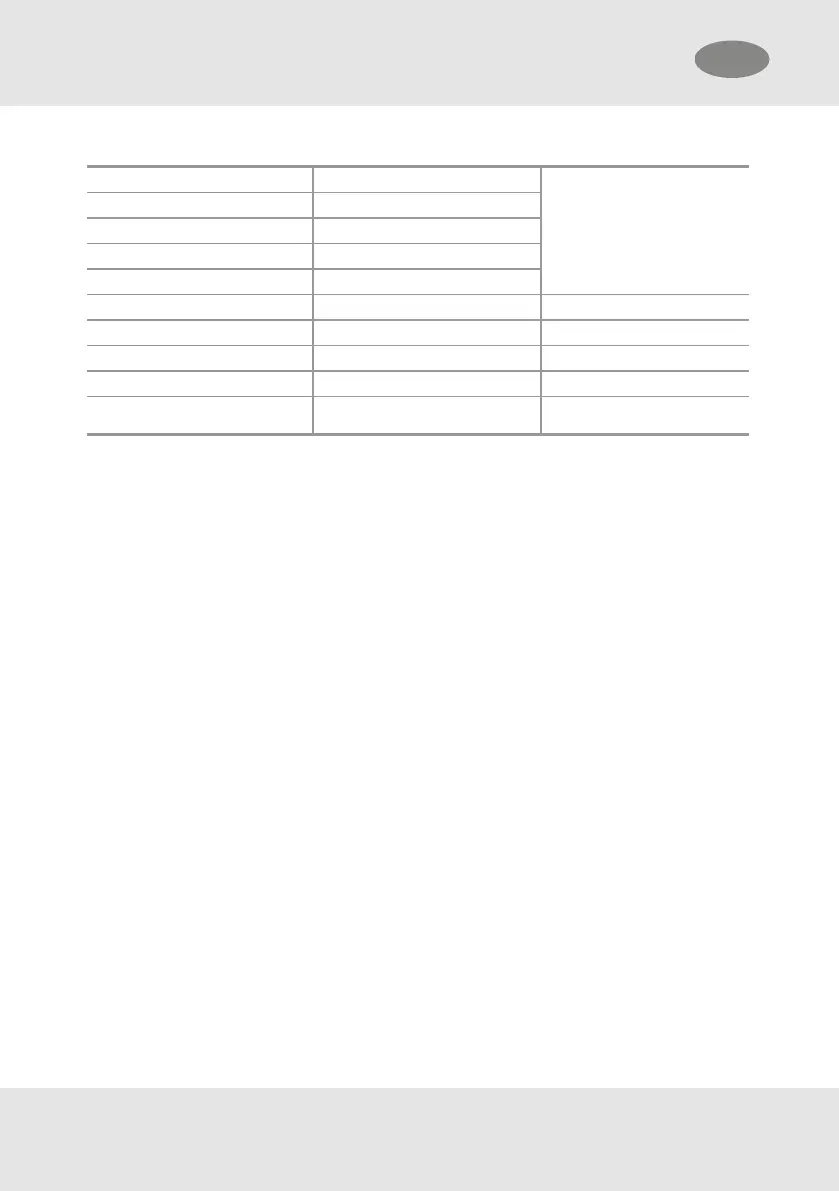
Table 1 System Requirement
COMPONENT EN / IRAM / NBR
Anchorage Connector EN 795* and/or CEN/TS 16415
Harness EN 361*
Connectors EN 362*
Structure Strength 12 kN
COMPONENT ANSI/OSHA CSA
Anchorage Connector Standard ANSI Z359.18 CSA Z259.13 / CSA Z259.15
Harness Standard ANSI Z359.11 CSA Z259.10
Connectors Standard ANSI Z359.12 CSA Z259.12
Structure Strength
3600 lbs (16 kN) certified
5000 lbs (22.5 kN) non-certified
5000 lbs (22.5 kN)
*Harmonised/Designated Standard
4.1 Fall Clearance
Ensure sufficient clearance exists to prevent striking an obstacle or leading edge (eg crossbeams and
girders) during a fall, insufficient clearance, obstructions and leading edges can prevent the function of the V-
TEC SRL.
To reduce the risk of a swing fall, where striking objects can cause serious injury, it is preferable to anchor
directly above the user.
The minimum fall clearance is 2.8 m (9.2 ft). Fall clearance is calculated as the vertical distance between the
working platform and the first obstacle below (such as the next platform or ground). Working limits vary
based on anchor location. Reference Table 2 Acceptable Anchor Locations.
If the V-TEC SRL is attached to an anchor that may deflect or deploy in a fall, such as a deadweight anchor or
anchor line, the additional deployment of that device shall be added to the minimum clearances specified in
Table 2 .
To reduce the potential for injury in a fall, the fall distance should be minimised.
V-TEC SRL 7
4 Installation and Use
GB