8
• “L” – 2400 baud (low);
• “M” – 9600 baud (medium);
• “H” – 19200 baud (high).
6) “TYPE” - voltage regulator connection type. The following protocol types are displayed: “BSS”
or one of the 12 types of “LIN” protocol: A1, A2, A3, A4, B1, B2, B3, B4, C3, D1, D2, E1.
7) "EXCITATION" – stator excitation level (load).
8) “ERROR” –voltage regulator operation errors. There are three types of potential errors:
• “EL” – electric error;
• “ME” – mechanic error;
• “TM” – thermal error.
When detected, the error is indicated in red.
9) “BACK” –diagnostic mode exit.
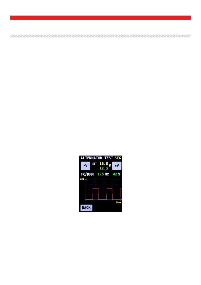
The following information will be displayed when the testing mode for one of the alternator types
("SIG”, “RLO”, RVC”, “C KOR.”, “P/D”, “C JAP.”) is selected: (Fig. 8):
1) Type of the tested alternator.
2) "-V" and "+V" buttons are used to set the voltage on the voltage regulator which is displayed as
"set + numerical value". Each press of the button changes the voltage value by 0.2V. The measured
voltage is displayed in green below the set voltage.
3) “FR” – Field response.
4) “DFM” – DFM – digital eld monitor.
Fig. 8. Alternator diagnostic window when one of the following alternator
types “SIG”, “RLO”, RVC”, “C KOR.”, “P/D”, “C JAP.” is selected.
User Manual - MS015 COM Tester
English