6
The cable has the following marking:
"GC" (Yellow) is intended for connection to the alternator voltage control terminal.
"FR" (Green) is intended for connection to the alternator load control terminal.
"-" (Black) - "B-." Battery negative pole (the alternator housing).
"+" (Red) - "B+". Battery positive pole, the alternator output. Used to power the device when
testing the alternator on the test bench or in the car; it is also used for “B+” voltage indication.
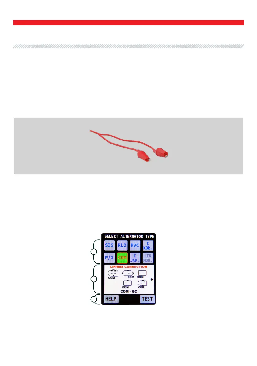
The main menu consists conditionally of three sections (Fig. 6):
Fig. 5. Cable for connection of additional “+”.
Fig. 6. Tester main menu.
4.1 Tester menu
1
2
3
User Manual - MS015 COM Tester
English