2-13
Hardware Setup
▍
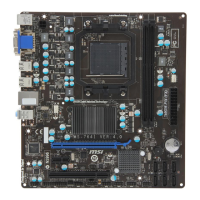
MS-7576
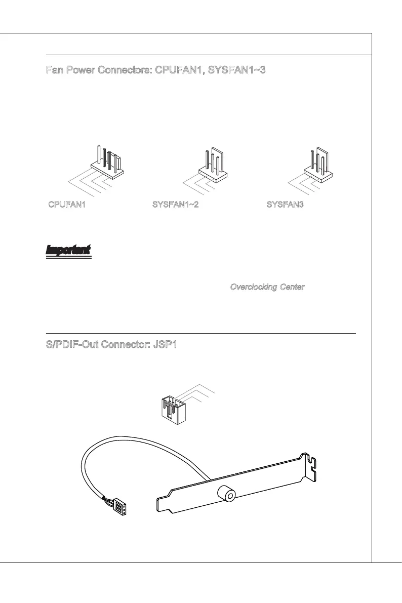
Fan Power Connectors: CPUFAN1, SYSFAN1~3
The fan power connectors support system coolng fan wth +12V. When connectng the
wre to the connectors, always note that the red wre s the postve and should be con-
nected to the +12V; the black wre s Ground and should be connected to GND. If the
manboard has a System Hardware Montor chpset on-board, you must use a specally
desgned fan wth speed sensor to take advantage of the CPU fan control.
1
.
G
r
o
u
n
d
2
.
+
1
2
V
3
.
S
e
n
s
o
r
4
.
C
o
n
t
r
o
l
CPUFAN1 SYSFAN3SYSFAN1~2
Important
Please refer to the recommended CPU fans at processor’s ocal webste or consult
the vendors for proper CPU coolng fan.
CPUFAN1 supports fan control. You can nstall
Overclockng Center utlty that wll
automatcally control the CPU fan speed accordng to the actual CPU temperature.
Fan cooler set wth 3 or 4 pns power connector are both avalable for CPUFAN1.
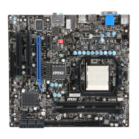
S/PDIF-Out Connector: JSP1
Ths connector s used to connect S/PDIF (Sony & Phlps Dgtal Interconnect Format)
nterface for dgtal audo transmsson.
S/PDIF Bracket (Optonal)
•
•
•