EasyManuals Logo

MSI 865PE Neo3-F User Manual

MSI 865PE Neo3-F
110 pages
To Next Page IconTo Next Page
To Previous Page IconTo Previous Page
Page #22 background imageLoading...
Page #22 background image
E-2-11
Hardware Setup
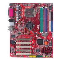
VGA Connector (Optional, for 865G only)
The mainboard provides a DB 15-pin female connector to connect a VGA
monitor.
VGA Connector
(DB 15-pin)
1
5
11
15
Pin Signal Description Pin Signal Description
1 RED 2 GREEN
3 BLUE 4 N/C
5 GND 6 GND
7 GND 8 GND
9 +5V 10 GND
11 N/C 12 SDA
13 Horizontal Sync 14 Vertical Sync
15 SCL
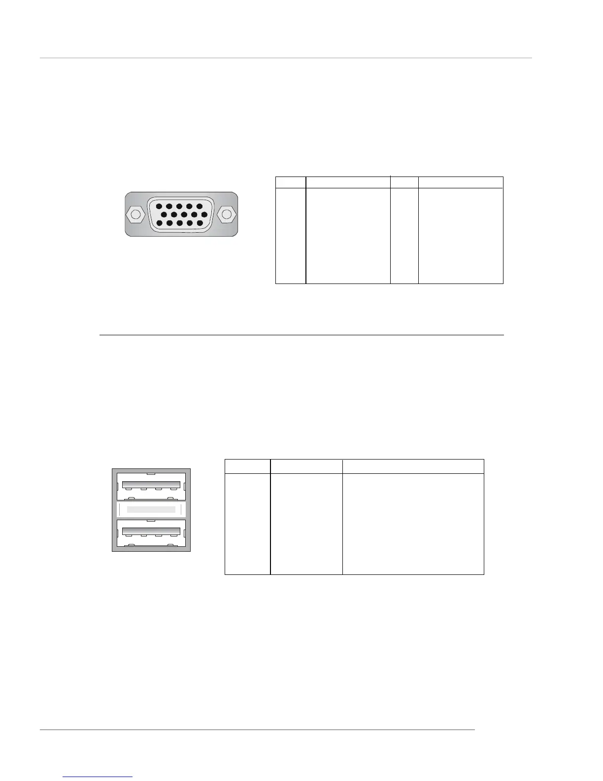
PIN SIGNAL DESCRIPTION
1 VCC +5V
2 -Data 0 Negative Data Channel 0
3 +Data0 Positive Data Channel 0
4 GND Ground
5 VCC +5V
6 -Data 1 Negative Data Channel 1
7 +Data 1 Positive Data Channel 1
8 GND Ground
USB Port Description
USB Connectors
The mainboard provides an OHCI (Open Host Controller Interface) Universal
Serial Bus root for attaching USB devices such as keyboard, mouse or other USB-
compatible devices. You can plug the USB device directly into the connector.
USB Ports
1 2 3 4
5 6 7 8

Questions and Answers:

Question and Answer IconNeed help?

Do you have a question about the MSI 865PE Neo3-F and is the answer not in the manual?

MSI 865PE Neo3-F Specifications

General IconGeneral
ChipsetIntel 865PE
SocketSocket 478
Supported CPUIntel Pentium 4 / Celeron
Front Side Bus800/533/400 MHz
Memory Slots4 x DIMM
Memory TypeDDR SDRAM
Max Memory4 GB
Expansion Slots1 x AGP 8X, 5 x PCI
Audio ChipsetRealtek ALC655
LAN Speed10/100Mbps
PS/22
Form FactorATX
Storage Interfaces2 x ATA100, 2 x SATA 1.5Gb/s
Audio Channels6 Channels
LAN ChipsetRealtek 8100C
USB Ports8 x USB 2.0 (4 rear, 4 via headers)

Related product manuals