Do you have a question about the MSI X79A-GD65 8D and is the answer not in the manual?
Legal information about the document's intellectual property and content accuracy.
Lists registered trademarks of various companies used in the manual.
Details the manual's revision history, starting with the first release date.
Provides resources and contact information for technical assistance.
Essential safety guidelines for handling and operating the equipment.
Compliance statement regarding radio frequency interference and corrective measures.
Guidance on battery disposal, handling, and replacement precautions.
Information on chemical substances in compliance with EU REACH regulations.
Warning regarding potential radio interference from Class A products.
Information on Waste Electrical and Electronic Equipment directive compliance.
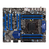
Details the supported Intel Core i7 processors and socket type.
Identifies the Intel X79 chipset used on the mainboard.
Specifies supported DDR3 DIMMs, speed, and maximum capacity.
Lists the supported LAN speed and Ethernet controller.
Details the integrated chip and available IEEE 1394 ports.
Specifies the integrated HD audio codec and channel support.
Lists the SATA ports by speed and controller.
Describes RAID support for SATA ports using Intel Rapid Storage Technology.
Details the number of USB 3.0 rear ports and onboard connector.
Mentions support for ATI CrossFireX and NVIDIA SLI technologies.
Lists all ports available on the mainboard's back panel.
Lists internal connectors and buttons on the mainboard.
Details the PCIe slots, their versions, and speeds.
States the mainboard's form factor (ATX) and mounting hole count.
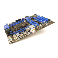
A visual guide showing the layout of the back panel connectors.
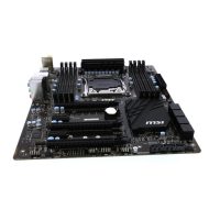
A diagram illustrating the placement of various connectors on the mainboard.
Details CPU socket and ATX power connectors with page references.
Information on memory slots and PCIe expansion slots with page references.
Details SATA and fan power connectors with page references.
Information on front panel, USB, and IEEE1394 connectors with page references.
Details chassis intrusion, audio, Voice Genie, and MultiConnect connectors with page references.
Information on OC Genie, Power, OC buttons, CMOS jumper, and low temp jumpers with page references.
Details the Multi BIOS switch and its page reference.
Describes the PS/2 combo port and Clear CMOS button.
Describes Coaxial and Optical S/PDIF-Out connectors for audio.
Details IEEE 1394 and USB 2.0 ports for device connectivity.
Describes USB 3.0 ports, backward compatibility, and data transfer rates.
Explains the RJ-45 LAN jack and its LED indicators for network status.
Details the color-coded audio ports and their specific sound functions.
Describes the LGA2011 CPU, alignment keys, and pin 1 indicator.
Warns about overheating and provides safety steps for CPU replacement.
Discusses overclocking support, performance, and associated risks.
Instructions for opening the hinge and active levers for cooler installation.
Steps to open the load plate by pushing the hinge lever.
Instructions for aligning the CPU and closing the load plate securely.
Steps for closing the active and hinge levers to lock the CPU.
Instructions for applying thermal paste and locating the CPU fan connector.
Steps for placing the heatsink and tightening screws for installation.
Final step to connect the CPU fan cable to the mainboard.
Guides on installing mounting stands and securing the mainboard in the case.
Key precautions for installing the mainboard to prevent circuit damage.
Details on connecting the ATX 24-pin power supply to the mainboard.
Explains the ATX 8-pin connector for CPU power delivery.
Details the ATX 4-pin connector for graphics card power.
Reminder about securely connecting power cables for stable operation.
Provides a link for information on compatible memory components.
Explains Quad-Channel mode support and its performance benefits.
Table showing DIMM slot mapping to memory channels.
Crucial notes on DDR3 compatibility, insertion order, and capacity detection.
Instruction to unlock the DIMM slot clip before inserting the module.
Guides on inserting the module until it clicks securely into place.
How to manually check if the memory module is locked in place.
Diagrams showing memory population for dual-channel configurations.
Diagrams illustrating memory population for triple-channel configurations.
Diagrams showing memory population for quad-channel configurations.
Key requirements for multi-channel stability like module type and slot usage.
Describes the PCIe 3.0 x16, 2.0 x16, and 2.0 x1 slots.
Important safety warning before installing or removing expansion cards.
Table detailing rules for installing graphics cards in PCIe slots.
Notes which graphics card configuration will display a POST message.
Details the high-speed SATA interface ports for storage devices.
Important advice on SATA device power, installation, and cable handling.
Explains the fan power connectors and their compatibility with system fans.
Key considerations for connecting system fans, including Smart Fan Control.
Details connectors for front panel switches and LEDs, including mConnectors.
Important notes on pin orientation and primary connector usage.
Describes USB 2.0 connectors for peripherals and MSI SuperCharger technology.
Key points on VCC/GND connection, single device charging, and SuperCharger availability.
Details the USB 3.0 port, its speed, and compatibility.
Important notes on VCC/GND connection and using compliant cables.
Explains the IEEE 1394 connector for connecting compatible devices.
Describes the chassis intrusion connector and its warning mechanism.
Details the front panel audio connector for case audio jacks.
Information on the optional voice control module connector.
Details the optional panel connector for OC Genie and other functions.
Lists points for measuring system voltages with a multimeter and their descriptions.
Explains the OC Genie button for automatic system overclocking.
Crucial notes for using OC Genie, including recommendations and risks.
Describes the power button functionality for turning the system on/off.
Explains the Plus/Minus buttons for adjusting Base clock frequency.
Details the JBAT1 jumper for clearing CMOS RAM and system configuration.
Important warning about clearing CMOS RAM only when the system is off.
Explains jumpers for extreme low temperature booting.
Warning for users attempting extreme low temperature overclocking.
Describes the switch for selecting between two BIOS ROMs.
Important warning not to use the BIOS switch when the system is powered on.
Indicates power phase status for CPU and memory modules.
Indicates DrMOS overheat and disk activity.
Indicates memory configuration issues in specific channels.
Provides status codes for system initialization and errors.
Explains the meaning of CPU phase LEDs based on CPU loading.
Explains memory phase and DrMOS overheat LEDs.
Explains HDD LED behavior and DIMM warning LEDs.
Table mapping POST codes to system initialization status and events.
Overview of the graphical BIOS interface and its features.
Instructions on how to enter the BIOS setup using DEL or F11 keys.
Notes that BIOS items are subject to change and for reference only.
Describes the main screen layout of CLICK BIOS II.
Reminder that pictures are for reference and actual screens may vary.
Shows CPU/mainboard temperatures and system details.
Describes how to navigate and select BIOS menus.
Explains managing boot device order and using the boot menu.
Features for presets and viewing/changing BIOS parameters.
Table detailing hot keys and mouse actions for BIOS navigation.
How to enter and exit sub-menus within the BIOS.
How to access the BIOS General Help window using F1.
Intro to OC Menu for advanced overclocking and usage warnings.
Displays current CPU and DRAM frequencies, read-only.
Adjusting PLL voltage and CPU Base clock for overclocking.
Adjusting CPU multiplier and Base Clock ratio.
Displays adjusted CPU freq and manages Intel SpeedStep.
Enables Turbo Boost and Direct OC buttons.
Adjusting DRAM frequency and enabling Extreme Memory Profile.
Selects DRAM timing control and enters advanced configuration.
Controls CAS latency, RAS to CAS delay, and precharge time.
Controls memory cell timings, write recovery, and read delays.
Controls active-to-active delay, read-precharge, activate window, and write latency.
Controls clock enable pulse width, round trip latency, and power down exit.
Section for setting read/write timings across different memory ranks.
Reduces EMI by modulating clock pulses; usage guidelines provided.
Controls load line droop for CPU current stream stability.
Adjusts voltages for CPU, Memory, and Chipset components.
Allows saving, loading, and managing overclocking profiles.
Displays key CPU features, specs, and technologies.
Displays DIMM settings, timings, and SPD info.
Entry point for CPU-specific feature settings.
Explains Hyper-Threading and its impact on system performance.
Allows selection of the number of active CPU cores.
Limits processor speed for older operating systems.
Prevents buffer overflow attacks by disabling code execution.
Enhances virtualization capabilities.
Selects power modes and enables CPU power saving when idle.
Monitors CPU power and manages idle power states.
Selects C-state mode and adjusts duration power limits.
Adjusts TDP limits for turbo modes and sets core ratio.
Step-by-step guide to update the BIOS using the Live Update utility.
Warning not to update the BIOS if the system is functioning correctly.
Describes the driver disc contents: drivers, utilities, info, and security.
Recommends visiting MSI's website for the latest software.
Step-by-step guide to install the Winki software from the driver disc.
| Socket | LGA 2011 |
|---|---|
| Chipset | Intel X79 |
| Form Factor | ATX |
| Max Memory Support | 64GB |
| Memory Type | DDR3 |
| PCI Express x16 Slots | 4 |
| USB 3.0 Ports | 4 |
| USB 2.0 Ports | 8 |
| SATA 6Gb/s | 2 |
| SATA 3Gb/s | 4 |
| Audio | Realtek ALC892 |
| PCI Express x1 Slots | 2 |
| LAN | Realtek RTL8111E |
| Memory Slots | 8 x DIMM |