E-2-19
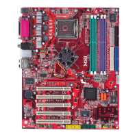
Hardware Setup
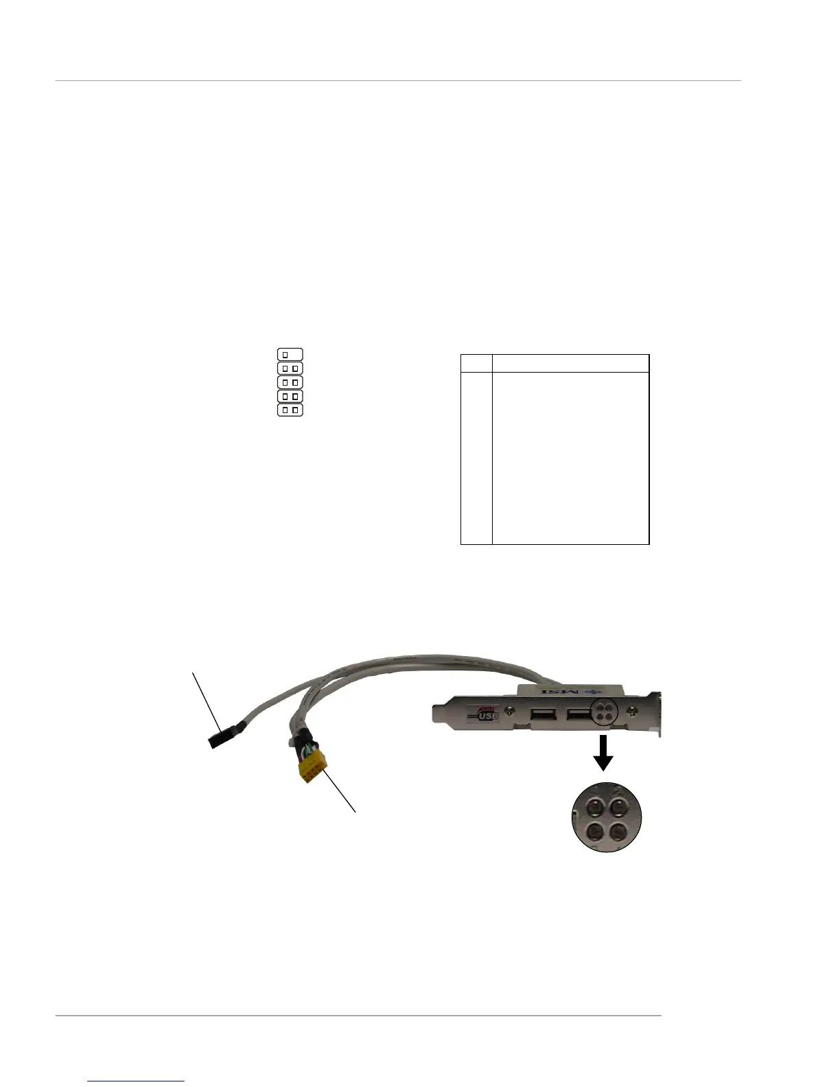
D-Bracket™ 2 Connector: JDB1
The mainboard comes with a JDB1 connector for you to connect to D-
Bracket™ 2, which supports both USB 1.1 & 2.0 spec.
D-Bracket™ 2 is a USB bracket integrating four Diagnostic LEDs, which use
graphic signal display to help users understand their system. The LEDs provide up to
16 combinations of signals to debug the system. The 4 LEDs can detect all problems
that fail the system, such as VGA, RAM or other failures. This special feature is very
useful for overclocking users. These users can use the feature to detect if there are
any problems or failures.
Pin Signal
1 DBG1 (high for green color)
2 DBR1 (high for red color)
3 DBG2 (high for green color)
4 DBR2 (high for red color)
5 DBG3 (high for green color)
6 DBR3 (high for red color)
7 DBG4 (high for green color)
8 DBR4 (high for red color)
9 Key (no pin)
10 NC
JDB1 Pin Definition
JDB1
1
9
2
10
Connected to JUSB1
Connected to JDB1
LEDs
Optional D-Bracket™ 2
 Loading...