E-2-24
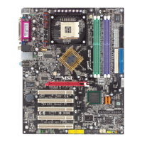
MS-6728 ATX Mainboard
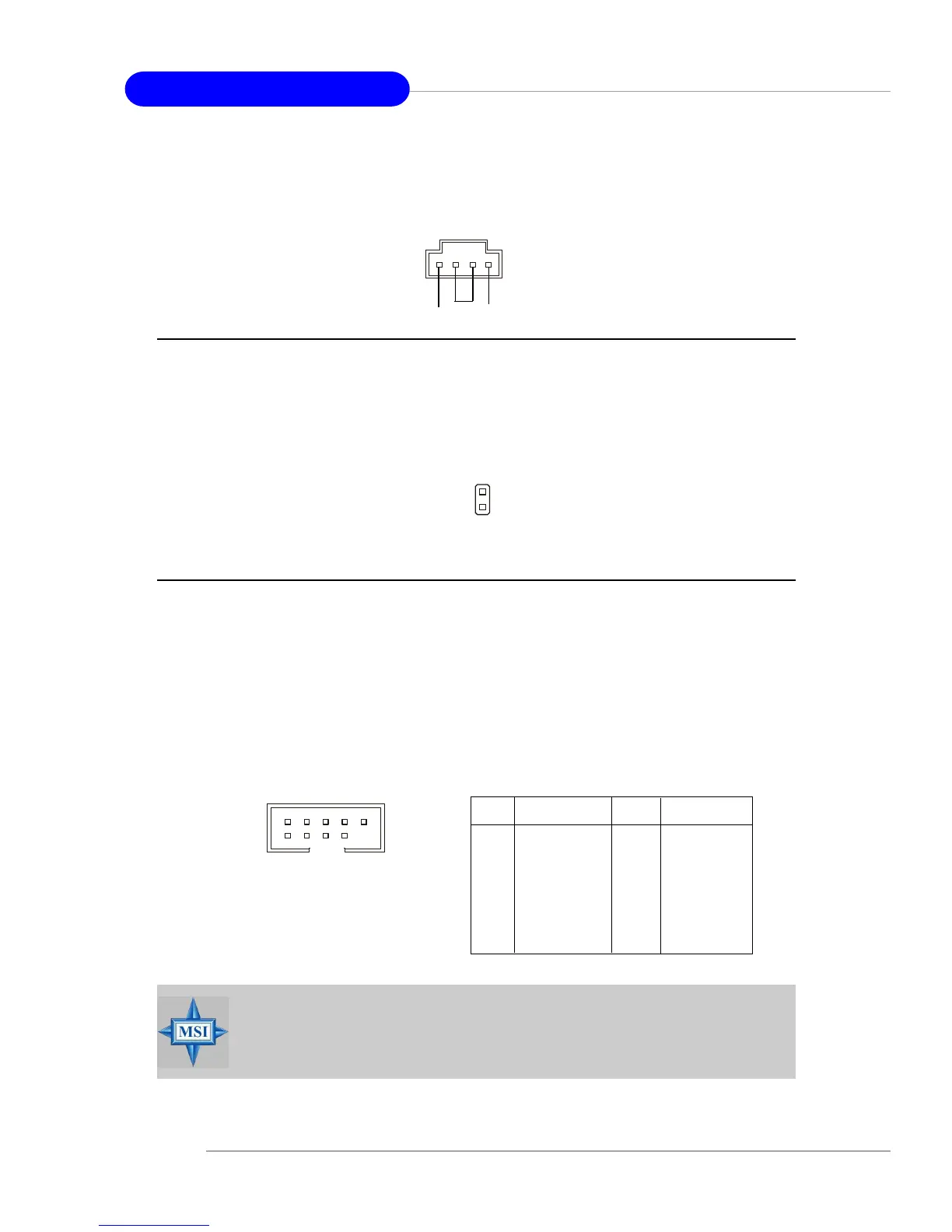
Chassis Intrusion Switch Connector: JCI1
This connector is connected to a 2-pin chassis switch. If the chassis is opened,
the switch will be short. The system will record this status and show a warning
message on the screen. To clear the warning, you must enter the BIOS utility and
clear the record.
JCI1
2
1
GND
CINTRU
Front USB Connectors: JUSB1 & JUSB2
The mainboard provides two USB 2.0 pin headers JUSB1 & JUSB2 (Optional)
that are compliant with Intel
®
I/O Connectivity Design Guide. USB 2.0 technology
increases data transfer rate up to a maximum throughput of 480Mbps, which is 40
times faster than USB 1.1, and is ideal for connecting high-speed USB interface
peripherals such as USB HDD, digital cameras, MP3 players, printers, modems
and the like.
PIN SIGNAL PIN SIGNAL
1 VCC 2 VCC
3 USB0- 4 USB1-
5 USB0+ 6 USB1+
7 GND 8 GND
9 Key (no pin) 10 USBOC
JUSB1 & JUSB2 Pin Definition
JCD1
GND L
R
CD-In Connector: JCD1
The connector is for CD-ROM audio connector.
JUSB2, JUSB1
(USB 2.0/Intel spec)
1
2
9
10
MSI Reminds You...
Note that the pins of VCC and GND must be connected correctly or
it may cause some damage.
 Loading...