2-15
Hardware Setup
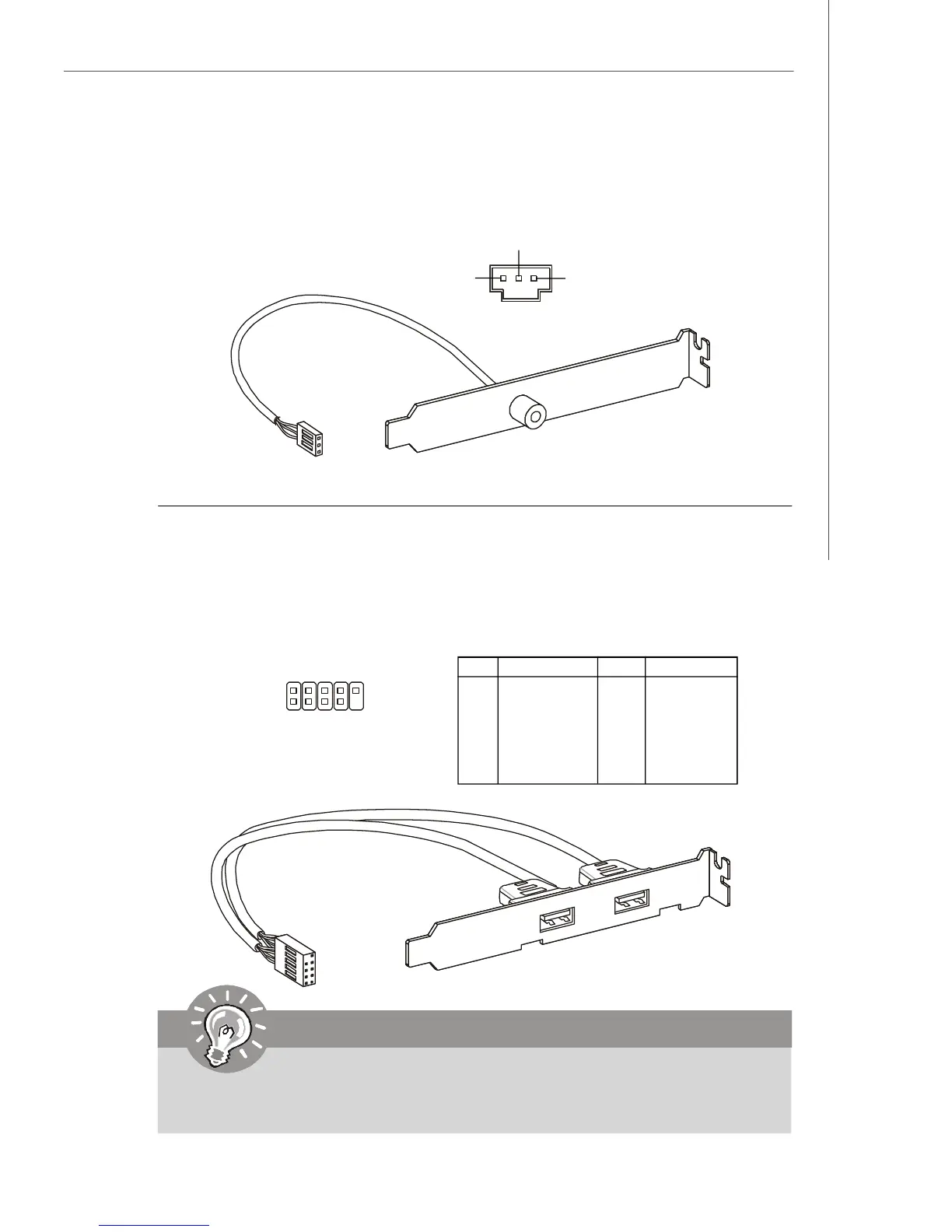
S/PDIF Bracket (Optional)
Front USB Connector: JUSB1, JUSB2, JUSB3
This connector, compliant with Intel
®
I/O Connectivity Design Guide, is ideal for con-
necting high-speed USB interface peripherals such as USB HDD, digital cameras,
MP3 players, printers, modems and the like.
PIN SIGNAL PIN SIGNAL
1 VCC 2 VCC
3 USB0- 4 USB1-
5 USB0+ 6 USB1+
7 GND 8 GND
9 Key (no pin) 10 USBOC
Pin Definition
Important
Note that the pins of VCC and GND must be connected correctly to avoid
possible damage.
1
2
9
10
JUSB1/2/3
USB 2.0 Bracket
(Optional)
S/PDIF-Out Connector: SPDOUT1 (Optional)
This connector is used to connect S/PDIF (Sony & Philips Digital Interconnect Format)
interface for digital audio transmission.
SPDOUT1
VCC
SPDIF
GND