EasyManua.ls Logo

MSI MEG Z390 ACE User Manual

MSI MEG Z390 ACE
96 pages
To Next Page IconTo Next Page
Page #1 background imageLoading...
Page #1 background image
1
Quick Start
DDR4 Memory
Graphics Card
SATA Hard Disk Drive
SATA DVD Drive
Phillips Screwdriver
Chassis
Power Supply Unit
A Package of Screws
Thermal Paste
Quick Start
Thank you for purchasing the MSI
®
MEG Z390 ACE motherboard. This Quick Start
section provides demonstration diagrams about how to install your computer. Some
of the installations also provide video demonstrations. Please link to the URL to watch
it with the web browser on your phone or tablet. You may have even link to the URL by
scanning the QR code.
Preparing Tools and Components
Intel
®
LGA 1151 CPU
CPU Fan

Table of Contents

Question and Answer IconNeed help?

Do you have a question about the MSI MEG Z390 ACE and is the answer not in the manual?

MSI MEG Z390 ACE Specifications

General IconGeneral
Processor socketLGA 1151 (Socket H4)
Processor manufacturerIntel
Compatible processor seriesIntel Celeron, Intel Core i3, Intel Core i5, Intel Core i7, Intel Pentium
Audio chipRealtek ALC1220
Component forPC
Motherboard chipsetIntel Z390
Audio output channels7.1 channels
Motherboard form factorATX
Windows operating systems supportedWindows 10
Non-ECCYes
Memory channelsDual-channel
Memory slots typeDIMM
Number of memory slots4
Supported memory typesDDR4-SDRAM
Maximum internal memory64 GB
Supported memory clock speeds2133, 2400, 2666, 2800, 3000, 3200, 3300, 3333, 3400, 3466, 3600, 3733, 3866, 4000, 4133, 4200, 4266, 4300, 4400, 4500 MHz
Supported memory module capacities16GB
PCI Express x1 (Gen 3.x) slots3
RAID levels0, 1, 5, 10
Supported storage drive typesHDD & SSD
Supported storage drive interfacesM.2, SATA III
Parallel processing technology support2-Way SLI, 3-Way CrossFireX
USB 2.0 connectors2
Number of SATA II connectors0
Number of SATA III connectors6
BIOS typeUEFI AMI
USB 2.0 ports quantityUSB 2.0 ports have a data transmission speed of 480 Mbps, and are backwards compatible with USB 1.1 ports. You can connect all kinds of peripheral devices to them.
USB 3.2 Gen 2 (3.1 Gen 2) Type-C ports quantity1
LAN controllerKiller E2500
Wi-Fi standards802.11a, 802.11b, 802.11g, Wi-Fi 4 (802.11n), Wi-Fi 5 (802.11ac)
Bluetooth version5.0
Ethernet interface typeGigabit Ethernet
Weight and Dimensions IconWeight and Dimensions
Depth244 mm
Width305 mm

Summary

Quick Start Guide

Preparing Tools and Components

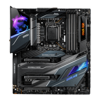
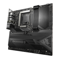
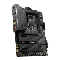
Identifies essential tools and components required for computer assembly.

Installing a Processor

Installing DDR4 Memory

Connecting the Front Panel Header

Installing the Motherboard

Installing SATA Drives

Installing a Graphics Card

Connecting Power Connectors

Power On Procedure

CPU Socket Installation and Precautions

LGA 1151 CPU Installation Guide

Guide to CPU notches and golden triangle for correct motherboard placement.

CPU and Heatsink Installation Safety

Critical safety and installation guidelines for CPU and heatsink.

DIMM Slots and Memory Installation

DIMM Slot Usage Recommendations

Recommendations for installing memory modules in the DIMMA2 slot first.

Memory Module Guidelines and Notes

Guidelines on memory capacity, voltage, and compatibility.

PCIe Expansion Slots and Multi-GPU

PCIe Slot Configurations and Usage

Information on PCIe lane configurations for single and multi-GPU setups.

Graphics Card Installation Advice

Advice on using graphics card support and safe installation practices.

Installing SLI Graphics Cards

M.2 Slots and Installation Procedures

Installing M.2 Modules (M2_1 & M2_2)

Procedure for installing M.2 SSDs into slots M2_1 and M2_2.

Installing M.2 Module with SHIELD FROZR (M2_3)

Procedure for installing M.2 SSDs into slot M2_3 with SHIELD FROZR.

M.2 Module Installation Details and Thermal Pads

SATA 6Gb/s Connectors and M.2 Combinations

Front Panel Connectors and GAME BOOST Knob

GAME BOOST Knob Functionality

Explanation of the GAME BOOST knob for manual overclocking stages.

Using the GAME BOOST Knob for Overclocking

Power Connectors and V-Check Points

ATX and CPU Power Connector Pinouts

Pinout and connection guide for ATX and CPU power supply cables.

USB 3.1 Gen1 Connectors and Charger Port

USB 3.1 Gen1 Front Panel Connectors (JUSB1, JUSB3)

Pinout and function of USB 3.1 Gen1 front panel connectors.

Fan Connectors and Speed Control

Fan Connector Pin Definitions (CPU, PUMP, SYS)

Pin definitions for various fan connectors and their modes.

Power/Reset Buttons and CMOS Jumper

Clearing CMOS Settings via JBAT1 Jumper

Procedure for clearing BIOS settings using the CMOS jumper.

RGB LED Connector Installation

RGB LED Connector Types and Usage

Information on connecting 12V RGB and 5V addressable RGB LED strips.

CORSAIR RGB Connector and Fan Hub

JCORSAIR1 Connector for CORSAIR Products

Details on connecting CORSAIR RGB fans and LED strips to the motherboard.

Onboard LEDs: Debug, DIMM, XMP, JPWRLED1

EZ Debug LED Functionality

Indicates motherboard debug status for CPU, DRAM, VGA, and Boot.

Debug Code LED and Boot Phase Codes

Debug Code LED Operation and Table

Displays progress and error codes during POST, with a reference table.

Installing OS, Drivers, and Utilities

Windows 10 Installation Steps

Step-by-step instructions for installing the Windows 10 operating system.

Driver and Utility Installation Guide

Procedure for installing motherboard drivers and system utilities.

MYSTIC LIGHT Software: LED Effects

Nahimic 3 Audio Software: Overview

BIOS Setup: Introduction and Navigation

Entering BIOS Setup Methods

Methods to access the BIOS setup utility.

BIOS Setup: Resetting and Updating

Resetting BIOS to Default Values

Steps to restore BIOS settings to factory defaults.

Updating BIOS via M-FLASH

Guide to updating BIOS using the M-FLASH utility.

Updating BIOS via MSI DRAGON CENTER

Procedure for updating BIOS using the MSI Dragon Center software.

BIOS Update via Flash BIOS Button

BIOS Setup: EZ Mode Configuration

EZ Mode Interface and Controls

Explanation of the EZ Mode interface elements and controls.

BIOS Setup: Advanced Mode Configuration

Advanced Mode Interface Overview

Explanation of the Advanced Mode interface and its main menu selections.

BIOS Menu Selection Options Explained

Details on SETTINGS, OC, M-FLASH, OC PROFILE, HARDWARE MONITOR, BOARD EXPLORER.

BIOS Setup: SETTINGS Menu

BIOS Setup: Boot Settings - Fast Boot and Secure Boot

Fast Boot and MSI Fast Boot Configuration

Settings for accelerating system boot times.

Secure Boot Configuration and Management

Settings for enabling and configuring Windows secure boot.

BIOS Setup: Boot Sequence and Security Features

BIOS Setup: Security Settings - Passwords

BIOS Setup: Security and Save & Exit Options

BIOS Setup: OC Settings - Overview

CPU Ratio and Frequency Adjustments

Adjusting CPU ratio and viewing the resulting frequency.

BIOS Setup: OC Settings - CPU Features

CPU Features for Overclocking: EIST, Turbo Boost

Settings related to Intel SpeedStep, Turbo Boost, and Enhanced Turbo.

CPU Base Clock and Clockgen Features

Adjusting CPU base clock and clock generation features.

BIOS Setup: OC Settings - Memory and Power

DRAM Frequency, Timings, and Fast Boot

Configuring DRAM frequency, timings, and enabling fast memory boot.

BIOS Setup: OC Settings - Voltages and CPU Specs

BIOS Setup: OC Settings - Virtualization and C-States

BIOS Setup: OC Settings - Power Limits and Intel Tech

M-FLASH BIOS Update Procedure

BIOS Setup: OC PROFILE Management

Hardware Monitor: System Monitoring

RAID Configuration: Introduction and Enabling RST

Enabling Intel® Rapid Storage Technology in BIOS

Steps to enable Intel RST for RAID functionality in BIOS.

RAID Configuration: Creating a Volume

RAID Configuration: Removing a Volume

RAID Configuration: Resetting Disks to Non-RAID

RAID Configuration: Rebuilding a Degraded Array

RAID Configuration: Driver and Software Installation

Installing Intel RAID Drivers

Steps for installing RAID drivers during OS installation.

Installing Intel RST Software

Guide to installing the Intel RST software after OS installation.

Intel® Optane™™ Memory Configuration: Installation

Installing the Intel Optane Memory Module

Step-by-step guide for installing Optane memory module and BIOS settings.

Intel® Optane™™ Memory Configuration: Enabling

Enabling Intel Optane Memory and Cautions

Procedure to enable Optane memory and critical warnings.

Intel® Optane™™ Memory Configuration: Removal

Disabling Intel Optane Memory

Steps to disable Optane memory via the RST application.

Removing the Optane Memory Module

Disabling M.2/Optane Genie and physically removing the module.

Troubleshooting: Common System Issues

Troubleshooting Power and Display Issues

Troubleshooting steps for no power or no display output.

Troubleshooting Boot, Audio, Network, USB

Solutions for boot failures, audio, network, and USB device issues.
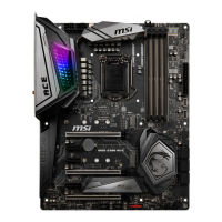
Related product manuals