35
Overview of Components
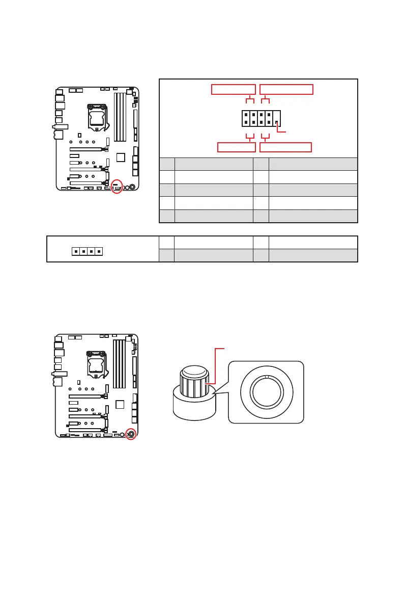
JFP1, JFP2: Front Panel Connectors
These connectors connect to the switches and LEDs on the front panel.
1
2 10
9
+
+
+-
--
-
+
Power LED
HDD LED Reset Switch
Reserved
Power Switch
JFP1
1 HDD LED + 2 Power LED +
3 HDD LED - 4 Power LED -
5 Reset Switch 6 Power Switch
7 Reset Switch 8 Power Switch
9 Reserved 10 No Pin
1
JFP2
1 Speaker - 2 Buzzer +
3 Buzzer - 4 Speaker +
GAME BOOST knob
0
1
2
4
6
8
1
0
1
1
OC1: GAME BOOST Knob
This knob allows you to manually select a stage from number 0 (default) to number 11
(extreme) for overclocking the processor. The processor’s voltage and frequency will
be automatically adjusted after you power on your computer.

 Loading...