2-13
Hardware Setup
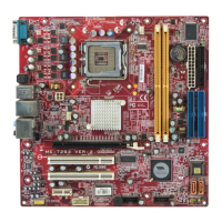
Fan Power Connectors: CPU_FAN1, SYS_FAN1
The fan power connectors support system cooling fan with +12V.
When connecting the wire to the connectors, always take note
that the red wire is the positive and should be connected to the
+12V, the black wire is Ground and should be connected to GND.
If the mainboard has a System Hardware Monitor chipset on-
board, you must use a specially designed fan with speed sensor
to take advantage of the CPU fan control.
Important
1.Please refer to the recommended CPU fans at Intel
®
official website or
consult the vendors for proper CPU cooling fan.
2.CPU_FAN1 supports fan control. You can install Core Center utility (refer
to Appendix for details) that will automatically control the CPU fan speed
according to the actual CPU temperature.
PIN SIGNAL PIN SIGNAL
1 VCC 2 VCC
3 USB0- 4 USB1-
5 USB0+ 6 USB1+
7 GND 8 GND
9 Key (no pin) 10 USBOC
Pin Definition
Important
Note that the pins of VCC and GND must be connected correctly to avoid
possible damage.
JUSB1/JUSB2
(USB 2.0)
1
2 10
9
Front USB Connectors: JUSB1, JUSB2
The mainboard provides two USB 2.0 pinheaders (optional USB 2.0 bracket available)
that are compliant with Intel
®
I/O Connectivity Design Guide. USB 2.0 technology
increases data transfer rate up to a maximum throughput of 480Mbps, which is 40
times faster than USB 1.1, and is ideal for connecting high-speed USB interface
peripherals such as USB HDD, digital cameras, MP3 players, printers, mo-
dems and the like.
SYS_FAN1
SENSOR
+12V
GND
CONTROL
CPU_FAN1
SENSOR
+12V
GND
CONTROL

 Loading...