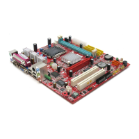
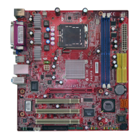
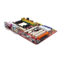
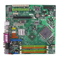
2-15
Hardware Setup
PIN SIGNAL DESCRIPTION
1 HD_LED + Hard disk LED pull-up
2 FP PWR/SLP MSG LED pull-up
3 HD_LED - Hard disk active LED
4 FP PWR/SLP MSG LED pull-up
5 RST_SW - Reset Switch low reference pull-down to GND
6 PWR_SW + Power Switch high reference pull-up
7 RST_SW + Reset Switch high reference pull-up
8 PWR_SW - Power Switch low reference pull-down to GND
9 RSVD_DNU Reserved. Do not use.
JFP1 Pin Definition
Front Panel Connectors: JFP1
The mainboard provides one front panel connector for electrical connection to the
front panel switches and LEDs. It is compliant with Intel
®
Front Panel I/O Connectivity
Design Guide.
1
2
9
10
JFP1
HDD
LED
Reset
Switch
Power
LED
Power
Switch
+
+
+
- -
-
IEEE 1394 Connectors: J1394_1
The mainboard provides IEEE1394 pinheaders that allow you to connect IEEE 1394
ports via an external IEEE1394 bracket (optional).
Pin Definition
PIN SIGNAL PIN SIGNAL
1 TPA+ 2 TPA-
3 Ground 4 Ground
5 TPB+ 6 TPB-
7 Cable power 8 Cable power
9 Key (no pin) 10 Ground
J1394_1
1
2
9
10
 Loading...