2-16
MS-7380 Mainboard
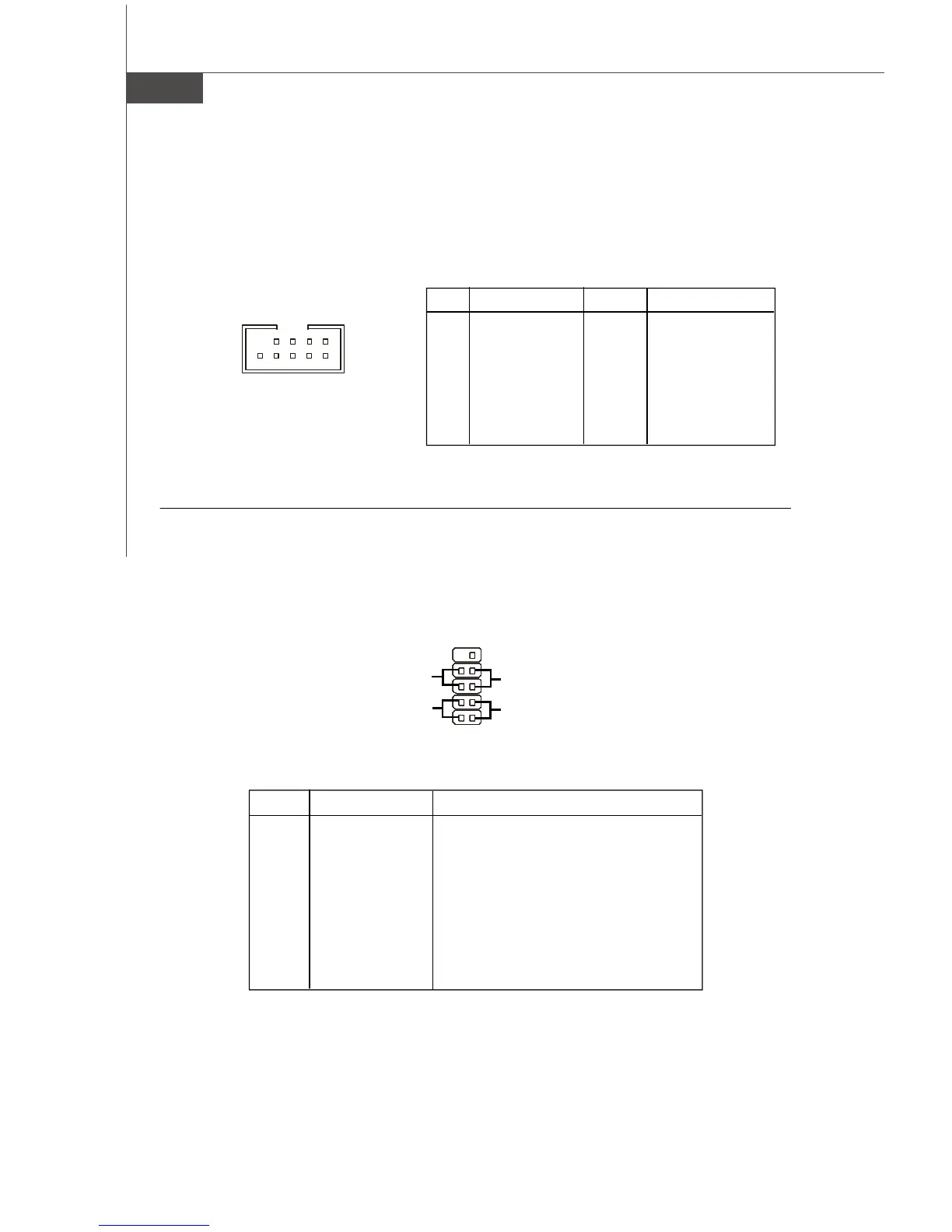
Front Panel Connector: JFP1
The connector is for electrical connection to the front panel switches and LEDs. The
JFP1 is compliant with Intel
®
Front Panel I/O Connectivity Design Guide.
PIN SIGNAL DESCRIPTION
1 HD_LED + Hard disk LED pull-up
2 FPPWR/SLP MSG LED pull-up
3 HD_LED - Hard disk active LED
4 FPPWR/SLP MSG LED pull-up
5 RST_SW - Reset Switch low reference pull-down to GND
6 PWR_SW + Po w e r S w i tc h hi gh re fe renc e p ul l- up
7 RST_SW + Reset Switch high reference pull-up
8 PW R_SW - PowerS witch low referencepull-down to GND
9 RSVD_DNU Reserved. Do not use.
JFP1 Pin Definition
1
2
9
10
JFP1
HDD
LED
Reset
Switch
Power
LED
Power
Switch
+
+
+
-
-
-
IEEE1394 Connector: J1394_1
This connector allows you to connect the IEEE1394 device via an optional IEEE1394
bracket.
Pin Definition
PIN SIGNAL PIN SIGNAL
1TPA+ 2 TPA-
3 Ground 4 Ground
5 TPB+ 6 TPB-
7 Cablepower 8 Cable power
9 Key(no pin) 10 Ground
J1394_1
1
9
2
10
 Loading...