Hardware Setup Industrial Computer Board
2-9
Hardware Setup Industrial Computer Board
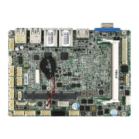
Front Panel Connector: JFP1
This front panel connector is provided for electrical connection to the front panel
switches & LEDs and is compliant with Intel Front Panel I/O Connectivity Design
Guide.
1.
+
3.
-
10.No
Pi
n
5.
-
Reset
S
wit
c
h
HDD
LE
D
P
ower
S
witch
P
ower
LE
D
7.
+
9.Reserve
d
8.
-
6.
+
4.
-
2.
+
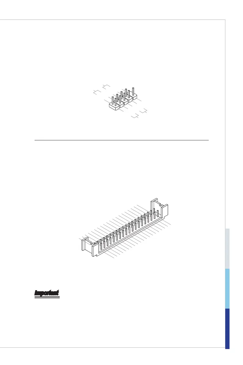
LVDS Connector: JLVDS1
The LVDS (Low Voltage Differential Signal) connector provides a digital interface
typically used with flat panels. After connecting an LVDS interface flat panel to
the JLVDS1, be sure to check the panel datasheet and set the LVDS jumper to
proper power voltage.
39.
LV
D
SB_CLK
#
27.
LV
D
SB_DA
TA
#1
25.
LV
D
SB_DA
TA
1
23.GN
D
21.
LV
D
SA_DA
TA
#3
19.
LV
D
SA_DA
TA
3
17.GN
D
15.
LV
D
SA_DA
TA
#1
13.
LV
D
SA_DA
TA
1
11
.L
VDS_BLON
9.L_BKL
T_CTRL#
7.
LV
DS_DDC_CLK
5.LCD_VDD
3.LCD_VDD
1.+12V
40.
LVD
SA_CLK
#
28.
LV
D
SB_DA
TA
#0
26.
LV
D
SB_DA
TA
0
24.GN
D
22.
LV
D
SA_DA
TA
#2
20.
LV
D
SA_DA
TA
2
18.GN
D
16.
LV
D
SA_DA
TA
#0
14.
LV
D
SA_DA
TA
0
12.
LV
DS_DETECT#_C
10.
LV
DS_VDD_E
N
8.
LV
DS_DDC_DA
TA
6.LCD_VDD
4.+12V
2.+12V
37.
LV
DSB_CLK
35.GN
D
33.
LV
D
SB_DA
TA
#3
31.
LV
D
SB_DA
TA
3
29.GN
D
38.
LV
D
SA_CLK
36.GN
D
34.
LV
D
SB_DA
TA
#2
32.
LV
D
SB_DA
TA
2
30.GN
D
Important
Pin 12 is a detect pin. When using a customized LVDS cable, pin 12 should be a
signal ground with a low impedance. Otherwise, LVDS will not function.
 Loading...