2-11
Hardware Setup
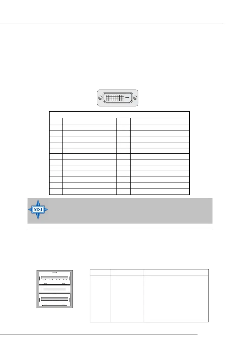
Digital Panel Connector
The mainboard provides a DVI (Digital Visual Interface) connector which
allows you to connect an LCD monitor. The DVI connector provides a high-speed
digital interconnection between the computer and its display device. To connect a
LCD monitor, simply plug your monitor cable into the DVI connector, and make sure
that the other end of the cable is properly connected to your monitor. (refer to your
monitor manual for more information.)
2417
Pin
1
2
3
4
5
6
7
8
9
10
11
12
DVI Connector
Signal Assignment
T.M.D.S.* Data2-
T.M.D.S. Data2+
T.M.D.S. Data2/4 Shield
T.M.D.S. Data4-
T.M.D.S. Data4+
DDC Clock
DDC Data
N/C
T.M.D.S. Data1-
T.M.D.S. Data1+
T.M.D.S. Data1/3 Shield
T.M.D.S. Data3-
Pin
13
14
15
16
17
18
19
20
21
22
23
24
Signal Assignment
T.M.D.S. Data3+
+5V
GND (for +5V)
Hot Plug Detect
T.M.D.S. Data0-
T.M.D.S. Data0+
T.M.D.S. Data0/5 Shield
T.M.D.S. Data5-
T.M.D.S. Data5+
T.M.D.S. Clock Shield
T.M.D.S. Clock+
T.M.D.S. Clock-
MSI Reminds You...
Please note that the DVI connector doesn’t support to connect the D-
Sub to DVI converter.
USB Connectors
The mainboard provides an OHCI (Open Host Controller Interface) Universal
Serial Bus root for attaching USB devices such as keyboard, mouse or other USB-
compatible devices. You can plug the USB device directly into the connector.
USB Ports
1 2 3 4
5 6 7 8
PIN SIGNAL DESCRIPTION
1 VCC +5V
2 -Data 0 Negative Data Channel 0
3 +Data0 Positive Data Channel 0
4 GND Ground
5 VCC +5V
6 -Data 1 Negative Data Channel 1
7 +Data 1 Positive Data Channel 1
8 GND Ground
USB Port Description