Ignition System
97
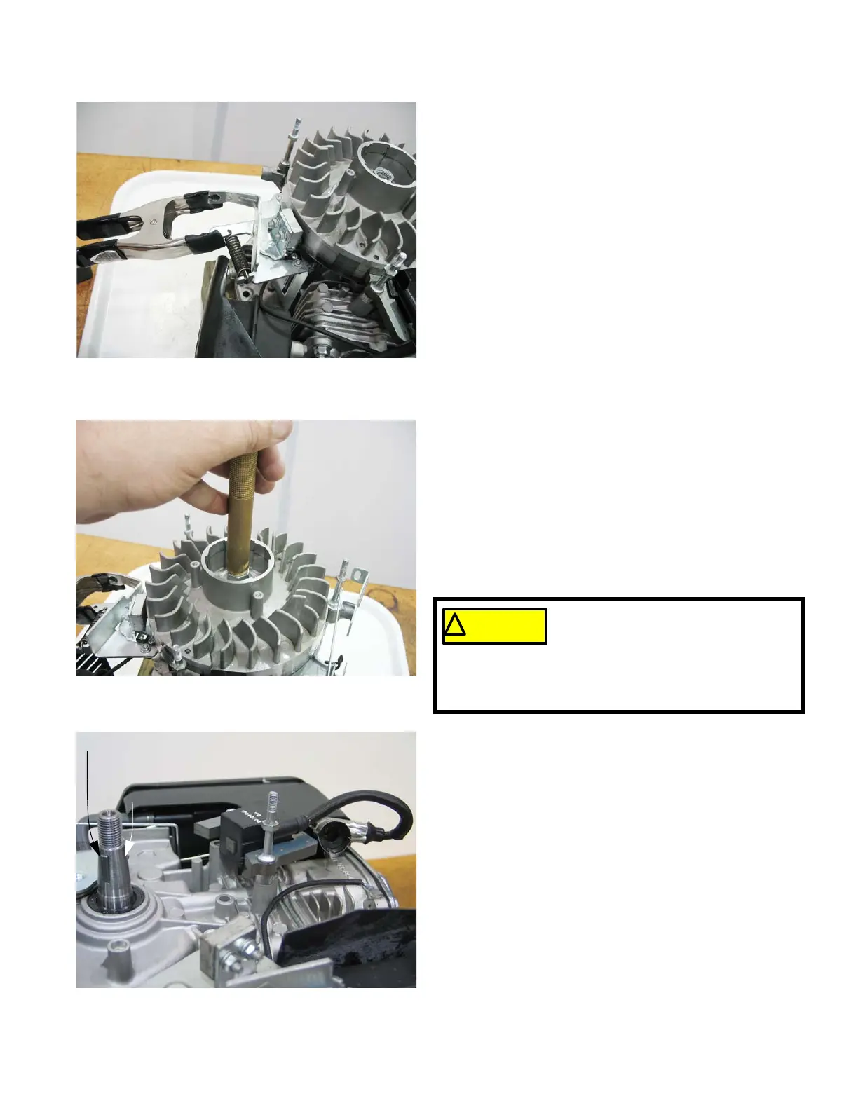
NOTE: If equipped with an engine brake, clamp off the
brake using a spring clamp. See Figure 7.25.
4. Remove the flywheel by applying a sharp blow to the
crankshaft using a brass drift punch and a hammer
while gently prying with a prybar. The flywheel will
“pop” loose then lift it off.
NOTE: Never strike the crankshaft directly with a hammer.
To prevent damage to the crankshaft use a brass
drift punch or a piece of wood between the ham-
mer and the crankshaft. See Figure 7.26.
5. Inspect the key, keyway, and tapered mating sur-
faces of the flywheel and crankshaft. See Figure
7.27.
NOTE: If the key is damaged it must be replaced. If there
is damage to the crankshaft key way, the engine
must be short blocked because crankshafts are
not available as a service part.
6. On installation, confirm that the key is properly
seated (the flat of the key parallel with the threaded
section of the crankshaft) in the key-way, and that
the tapers are fully seated. Key or keyway failure
may result from improper seating.
If the flywheel shows any signs of
physical damage such as cracks, bro-
ken vanes (if equipped), or a damaged
keyway, replace it. A damaged flywheel poses a
threat of a burst failure. Burst failures are extremely
hazardous to surrounding people and property.
Figure 7.27
Key flat parallel to the threads
Taper
 Loading...


