FUEL SYSTEM AND GOVERNOR
59
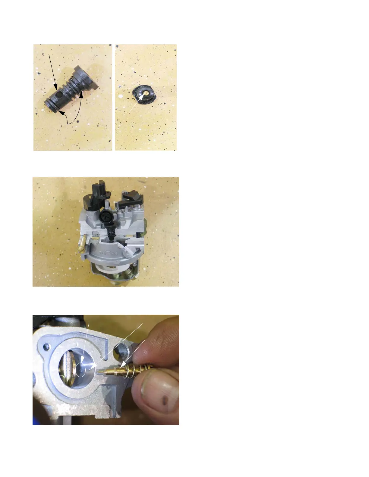
9. Examine the metering plug: See Figure 4.52.
• Fuel, drawn from the central column via the long
fuel feed leg, is metered by the brass orifice in the
tip of the metering plug.
• Air, drawn from the emulsion air port, is metered by
the size of the brass orifice at the entrance to the
port.
• The fuel and air that feed the pilot and transition
ports are mixed at the metering plug.
• The metering plug creates a small venturi. The
pressure drop of the air passing through the meter-
ing plug draws the fuel into the passage to the pilot
and transition ports, in an emulsified mixture.
NOTE: In cut-away view, the passage by the metering port
is visible. See Figure 4.53.
NOTE: The pilot screw regulates how much of this pre-
mixed fuel/air emulsion is allowed to enter the
throat of the carburetor, to atomize down-stream of
the throttle plate. On early production carburetors
the pilot screw is serviceable, but on current pro-
duction units it is set at the factory with Loctite to
prevent movement from vibration. The screw head
is removed to meet EPA and CARB requirements.
See Figure 4.54.
NOTE: The transition ports are fixed. They are drilled into
the throat of the carburetor, down-stream of the
venturi. They lie behind the brass welch plug near
the pilot screw.
End view
Fuel metering orifice
Figure 4.54
Transition ports Pilot port
Pilot screw
(old style)