14
INM5000-6 Jul 2010
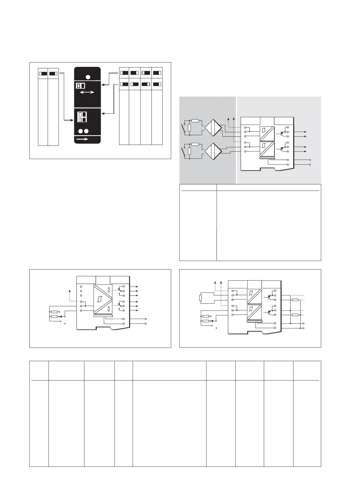
6.4.2 Outputs
The output 1 relay reflects the status of the input and may be configured
to operate in reverse phase (PR) or with line-fault detection (LF). The
output 2 relay may be configured either to follow (slave mode) output 1
or as a line-integrity monitor (LFD) (see 6.4.3).
6.4.3 Line fault detection
(See section 3.1.4 for definition of a line fault)
Line-fault detection and the operational mode of output 2 (ie slave to
output 1 or LFD) are selected by switches located on the top of the
module (see figure 6.8).
When LFD is selected for output 2 and there is a line fault in the sensor
circuit the output 2 relay is de-energised (providing an alarm output).
When LF is selected for output 1, the output 1 relay is de-energised if
there is a line fault in the sensor circuit. Note that resistors must be fitted
when using LFD with a contact input; 500Ω to 1kΩ in series, and 20kΩ
to 25kΩ in parallel with the switch.
6.4.4 Testing
Make the relevant safe- and hazardous-area connections shown in figure
6.9 for the tests listed in table 6.3. (Figure 6.8 shows the switch positions
for configuring output 2 slave/LFD, output 1 line fault (LF) and phase
reversal (PR)).
Table 6.3
6.5 MTL5015 solid-state two-channel
switch/proximity detector with line
fault detection and phase reversal
The MTL5015 enables each of two safe-area loads to be controlled,
through a solid-state output, by a switch or proximity detector in a
hazardous area. Line fault detection (LFD) and output phase reversal
(see 3.1.3) facilities are included.
6.5.1 Wiring connections
See figure 6.10 for wiring connections.
Phase Line fault Output 1 Output 2 Status Fault
reverse detection Slave Input test switch position relay relay LED LED
Test switch (PR) (LF) (LFD) (terminals 1 & 2) (11-12) (9-8) (yellow) (red)
1 Normal Off LFD (a) i.e. short-circuit Closed Open On On
2 Reverse Off LFD (a) short-circuit (I
sc
=7–9mA) Open Open Off On
3 Normal On Slave (a) short-circuit Open Open Off On
4 Normal Off Slave (a) short-circuit Closed Closed On Off
5 Normal Off Slave open-circuit (V
oc
=7V5–9V5) Open Open Off Off
6 Normal On Slave open-circuit Open Open Off On
7 Normal Off LFD (b) 22kΩ Open Closed Off Off
8 Normal Off LFD (c) 680Ω Closed Closed On Off
Artisan Technology Group - Quality Instrumentation ... Guaranteed | (888) 88-SOURCE | www.artisantg.com