6.13 MTL5024 solenoid/alarm driver,
logic drive with phase reversal
The MTL5024 enables an on/off device located in a hazardous area to
be controlled by a volt-free contact or logic signal located in t he safe
area. Output phase reversal (see 3.1.3) facilities are included.
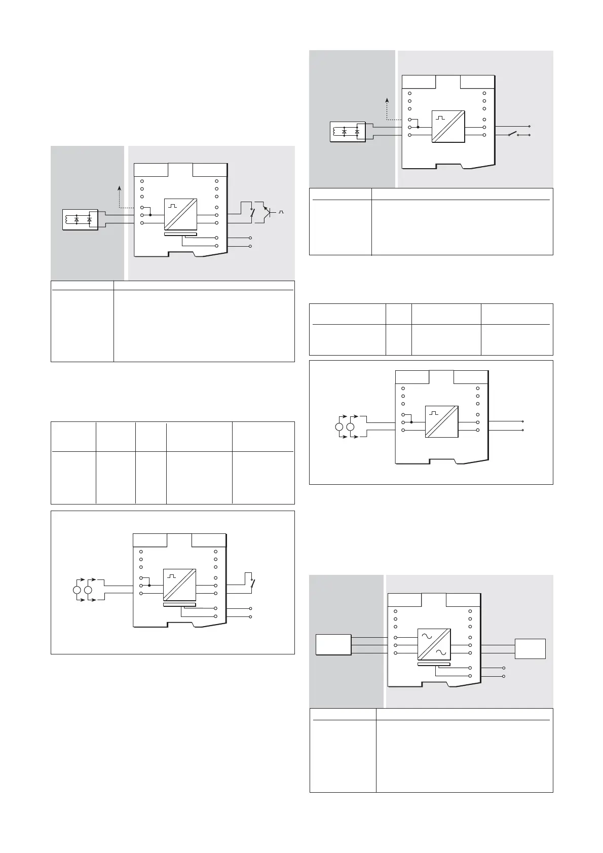
6.13.1 Wiring connections
See figure 6.26 for wiring connections.
6.13.2 Testing
Make the safe- and hazardous-area connections shown in figure 6.27
and carry out the following output voltage and short-circuit current
checks:
6.14 MTL5025 low-current loop-powered
solenoid/alarm driver, IIC
The MTL5025 enables an on/off device located in a hazardous area to
be controlled by a switch or voltage change in a safe area.
6.14.1 Wiring connections
See figure 6.28 for wiring connections.
19
INM5000-6 Jul 2010
6.14 .2 Testing
Make the safe- and hazardous-area connections shown in figure 6.29
and carry out the following output voltage and short-circuit current
checks:
6.15 MTL5031 vibration transducer
interface
The MTL5031 repeats the signal from a vibration sensor in a hazardous
area to a monitoring system in a safe area.
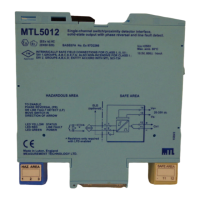
6.15.1 Wiring connections
See figure 6.30 for wiring connections.
Terminal Function
1 Output –ve
2 Output +ve
3 Earth leakage detection
11 Control –ve
12 Control +ve
13 Supply –ve
14 Supply +ve
Figure 6.26: MTL5024 wiring diagram and connections
SW1 Output Output
(terminals Phase Status voltage current
11 & 12) setting LED (terminals1 & 2) (terminals 1 & 2)
Closed Normal On 22 to 24V —
Closed Normal On — 45 to 52mA
Closed Reverse On — <6mA
Artisan Technology Group - Quality Instrumentation ... Guaranteed | (888) 88-SOURCE | www.artisantg.com