Temposonics
®
E-Series
Brief Instructions
I 8 I
4.1 Sensor mounting
NOTICE
For detailed mounting instructions see operation manual.
Sensors with stroke lengths ≥ 1 meter (≥ 3.3 ft)
Support horizontally installed sensors with a stroke length
from 1 meter (3.3 ft) mechanically at the rod end. Without the
use of a support, rod and position magnet may be damaged.
A false measurement result is also possible.
Longer rods require evenly distributed mechanical support
over the entire length (e.g. part no. 561 481).
Use an U-magnet for measurement.
Mounting clamps
Screw: M5×20 (DIN 6912)
Sensor support
(for sensors with stroke lengths ≥ 1 meter (≥ 3.3 ft))
U-magnet
Sensor rod
Non-magnetic fixing clip
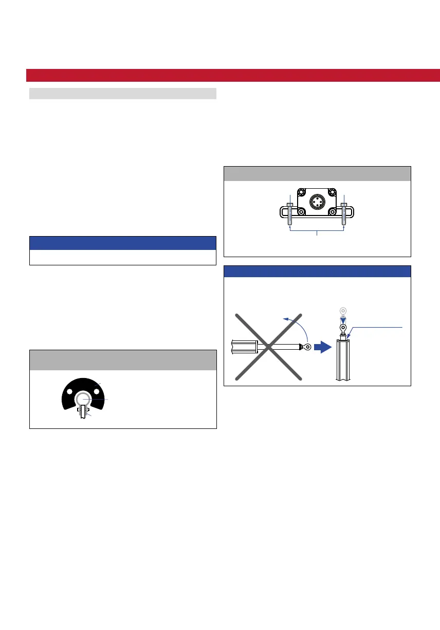
NOTICE
Do not raise up the ER sensor, if the lifting rod is
extended.
It causes
serious damage
Rod sensors – E-Series EH
• Fix the sensor rod via threaded flange.
• Note the fastening torque of 50 Nm.
• Seat the flange contact surface completely on the cylinder
mounting surface
• The cylinder manufacturer determines the pressure-
resistant gasket (copper gasket, O-ring, etc.).
• The position magnet should not grind on the sensor rod.
• The piston rod drilling
(Ø 10 mm rod: ≥ Ø 13 mm (≥ Ø 0.52 in.) borehole /
Ø 7 mm rod: ≥ Ø 10 mm (≥ Ø 0.4 in.) borehole)
depends on the pressure and piston speed.
• Adhere to the information relating to operating pressure.
• Protect the sensor rod against wear.
Profile sensors – E-Series EP / EL / ER / EP2
The sensor is fitted on a flat machine surface using mounting
clamps. A length-dependent number of these clamps are
delivered with the sensor and must be distributed over the
profile at regular distances.
For fastening, we recommend using M5×20 screws
(according to DIN 6912) that should be tightened with
a fastening torque of 5 Nm.
4. Installation & mounting

 Loading...


