Checking valve clearance at two crankshaft positions
1. Check TDC position of piston in cylinder A1:
• If the rocker arms are unloaded on cylinder A1, the piston is in firing TDC.
• If the rocker arms are loaded on cylinder A1, the piston is in overlap TDC.
2. Check valve clearance with cold engine:
• Inlet (E) = 0.3 mm;
• Exhaust (A) = 0.4 mm.
3. Check all valve clearances at two crankshaft positions (firing TDC and overlap TDC) according to the table
below.
12 V 2000
Position Cylinder 1 2 3 4 5 6 7 8
Firing TDC in cylinder A1 Bank A E A E - - A E - - A - -
Bank B E - - - - A E - E A - A
Overlap TDC in cylinder A1 Bank A - - - A E - - A E - E A
Bank B - A E A E - - A - - E -
“E” = inlet valve clearance adjustment permitted, “A” = exhaust valve clearance adjustment permitted
16 V 2000
Position Cylinder 1 2 3 4 5 6 7 8
Firing TDC in cylinder A1 Bank A E A - A E A E - - A E - - - - -
Bank B E - - A - - - - E A E - E A - A
Overlap TDC in cylinder A1 Bank A - - E - - - - A E - - A E A E A
Bank B - A E - E A E A - - - A - - E -
“E” = inlet valve clearance adjustment permitted, “A” = exhaust valve clearance adjustment permitted
4. Use feeler gauge to determine the distance between valve bridge and rocker arm.
5. If the deviation from the reference value exceeds 0.1 mm, adjust valve clearance.
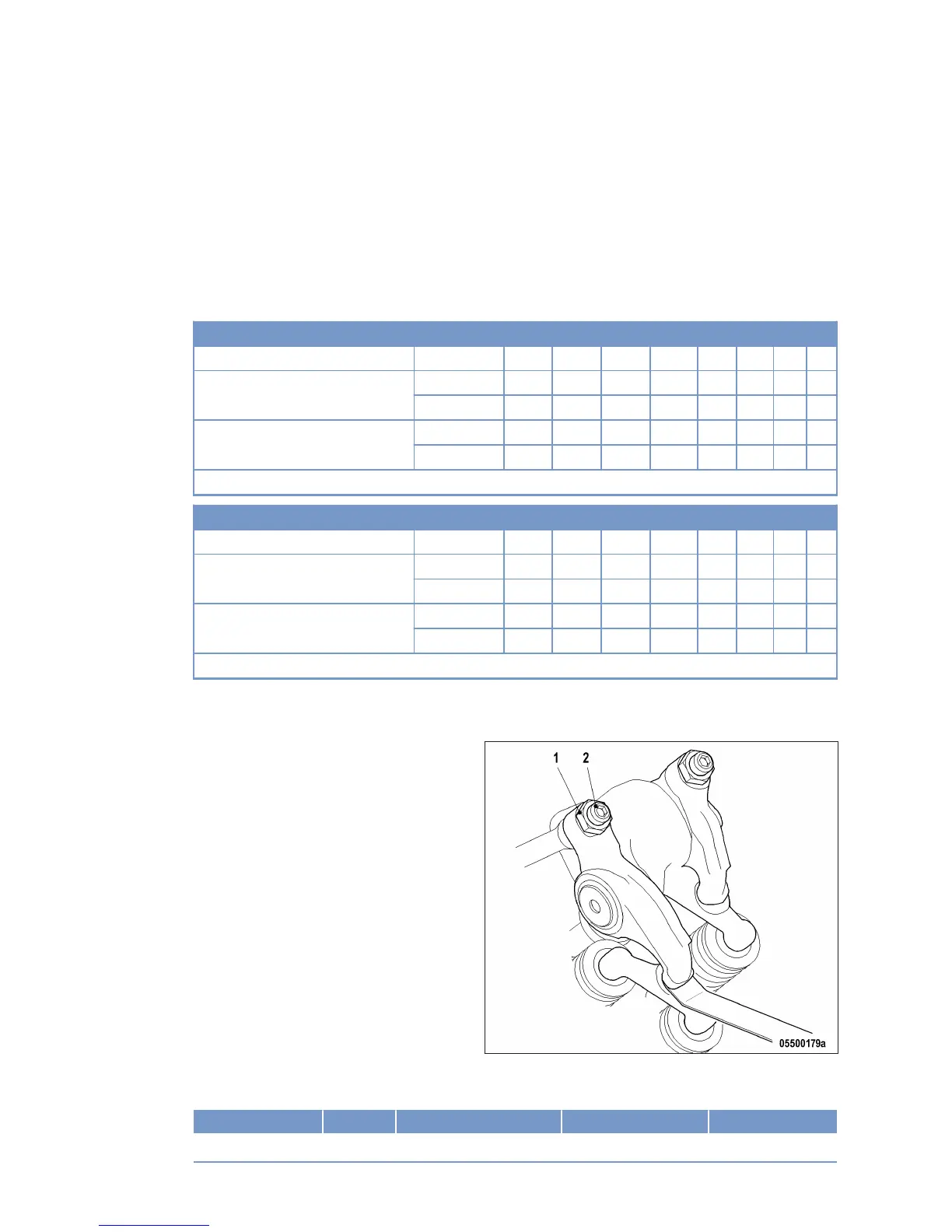
Valve clearance adjustment
1. Loosen locknut (1) and unscrew adjusting
screw (2) by a few threads.
2. Insert feeler gauge between valve bridge and
rocker arm.
3. Readjust adjusting screw (2) so that the feel-
er gauge just passes through the gap.
4. Tighten locknut (1) with torque wrench to the specified tightening torque, holding the adjusting screw (2)
with Allen key to prevent it from turning.
Name Size Type Lubricant Value/Standard
Locknut Tightening torque 50 Nm +5 Nm
78 | Task Description | MS150094/02E 2015-05
TIM-ID: 0000023895 - 004