Do you have a question about the Mueller ISOBUS SPRAYER-Controller MAXI 3.0 and is the answer not in the manual?
Covers essential safety guidelines for operating and servicing the system, emphasizing user responsibility and product integrity.
Explains the standardized format for safety warnings, including signal words like WARNING and CAUTION, to convey hazard levels.
Describes the structure and purpose of alarm messages, detailing how they warn operators about dangerous situations or incorrect configurations.
Outlines the necessary qualifications and responsibilities of users, including reading instructions and seeking clarification when needed.
Defines the product's purpose in agricultural spraying and clarifies the manufacturer's liability regarding misuse or unauthorized modifications.
Provides instructions for the proper disposal of the product as electronic scrap in accordance with waste management laws.
Details the importance and placement of safety signs on the field sprayer to warn individuals about potential dangers.
Illustrates safety stickers found on the product and provides information on their meaning and proper maintenance.
States the product's compliance with EC directives, particularly Electromagnetic Compatibility (EMC) regulations.
Identifies the intended audience for the manual, focusing on operators of SPRAYER-Controller MAXI/MIDI 3.0 systems.
Specifies the product versions (SPRAYER-Controller MAXI or MIDI 3.0, Software version 7.5s) to which these instructions apply.
Explains that screenshots serve as references and may differ based on sprayer configuration and terminal type.
Describes the step-by-step approach used in the manual and the symbols employed to denote actions and sequences.
Explains how cross-references are presented in the manual, typically using square brackets and arrows to point to other sections.
Details the abbreviations and information found on the product's rating plate, such as item numbers, hardware/software versions, and operating voltage.
Provides a step-by-step procedure to access and identify the current software version of the job computer.
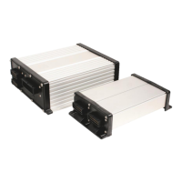
Explains the system architecture, including main systems and extensions like DISTANCE-Control II, TANK-Control II, and EDS.
Provides crucial safety guidelines and precautions to follow during the installation process of the job computer and related components.
Details the procedure for connecting the job computer to the tractor's ISOBUS power socket for power and communication.
Describes the procedures for powering the job computer on and off, including steps for both ISOBUS and non-ISOBUS tractors.
Guides users through the first-time startup process of the job computer after installation and connection to the terminal.
Explains how the job computer appears and is registered within the terminal's selection menu.
Details the layout of the work screen, including areas like spray data, boom display, and function icons.
Explains the options for operating the job computer, such as using screen buttons, the ME joystick, or the ME S-Box.
Covers methods for entering new tank content, including manual filling and using TANK-Control systems.
Explains how to operate the sprayer boom, including lifting, lowering, locking, folding, and adjusting boom sides.
Details the process of starting the spraying application in both manual and automatic modes, including prerequisite checks.
Explains how to regulate the application rate manually or automatically, including mode switching and target rate adjustment.
Outlines the options available to stop the spraying application, such as closing the main valve or reducing speed.
Describes how to operate individual sections of the sprayer, including opening and closing them manually.
Explains the 'Localized mode' for targeted weed treatment, allowing individual section control even if not adjacent.
Details how to use the ME joystick to activate and deactivate sprayer functions, including preview modes and button assignments.
Explains how to operate the foam markers, which help drivers maintain parallel paths on the field.
Covers manufacturer-specific functions that can be activated or deactivated via additional screens or buttons.
Describes the AIRTEC system for regulating drop size by adjusting air pressure, covering manual and automatic modes.
Explains the configuration settings for joystick and S-Box control units, including parameter options like 'Joystick' and 'ME S-Box'.
Provides a table outlining key configuration steps required during initial setup, referencing detailed sections for each task.
Guides users on setting essential field sprayer parameters like nozzle type, rate, working width, and sensor configurations.
Details how to configure compatibility with various ISOBUS terminals, including settings for serial numbers and work states.
Explains the necessity and procedures for calibrating the flow meter using either the tank method or the nozzle method.
Covers selecting the speed source (Sensor or ISOBUS) and calibrating the speed sensor using the 100m method.
Details how to configure sections, including entering nozzle counts, switching sections off, and setting system delays.
Explains nozzle assistant functions, setting intended rates, and calibrating nozzles for pressure sensor-based regulation.
Describes the use and configuration of extremity nozzles (corner or wide area) for managing spray width at boom ends.
Explains modes for configuring multiple nozzle holders, including automatic nozzle selection and manual activation.
Guides on selecting the correct nozzle number for AIRTEC configuration to ensure proper drop size regulation.
Details how to measure and input sprayer dimensions to accurately map the implement's layout for software calculations.
Provides steps for calibrating sensors to ensure accurate detection and display of the boom's position and slope.
Explains configuration for sprayers with two job computers, including identifying main/auxiliary systems and setting geometry.
Allows users to select and configure display units (metric/imperial) and decimal settings for various parameters.
Guides users through adjusting TRAIL-Control parameters to adapt the system to different tractors and optimize steering.
Explains how to operate TRAIL-Control in automatic and manual modes, including steering, centering, and reverse driving functions.
Lists and explains error messages related to axle height sensors, drawbar sensors, and suspension calibration.
Details alarm messages for the AIRTEC system, including pressure issues, speed variations, and nozzle problems.
Covers alarm messages related to the DISTANCE-Control system, particularly during calibration and operation phases.
Explains alarm messages associated with the boom functionality, such as transport position, locking, and height control.
Lists alarm messages related to the overall sprayer status, including tank level, pump speed, oil level, and compressor issues.
Describes alarm messages pertaining to the application rate control, such as out-of-reach rates, pressure variations, and flow meter issues.
Covers general system alarms, including password requirements and issues with external device operation.
Details alarm messages related to the TRAIL-Control system, including sensor faults, calibration issues, and steering problems.
Explains alarm messages specific to the Vario-Select system, such as nozzle overlap issues and requirements for nozzle setup.
| Brand | Mueller |
|---|---|
| Model | ISOBUS SPRAYER-Controller MAXI 3.0 |
| Category | Controller |
| Language | English |