M0160.docx | Rev 1.3 | Last modified 19/05/2020 | © Remote Control Technologies Pty Ltd
Installation Guide
Note
If the EPS system is installed in conjunction with an idle timer and/or a fire status control unit, it is imperative
that the units are installed in the correct order. Failure to do so may result in the machine not shutting down
correctly.
Refer to the appendix at the end of this manual for the correct sequence.
Control Unit
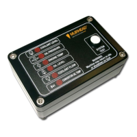
1. The recommended location for the control unit is in the operator’s cabin in clear view and within easy reach
of the operator. Proximity to the operator is important as the control unit incorporates a system test
switch/circuitry that allows service personnel and/or operators to test the system.
2. Drill two 8 mm diameter holes with the hole centres being 100 mm apart to suit the M8*30 hex screws that
bolt to the control unit mounting bracket. Careful consideration should be given to the location of these
holes before drilling to ensure adequate accessibility to the electrical connection located on the rear of the
control unit.
3. Refer to the wiring table below and the wiring diagram in this manual to wire up the control unit. It is
recommended that the wiring loom be installed alongside the OEM engine wiring ensuring that it is secured
at regular intervals; this will provide protection from heat and abrasion, and any other excess damage that
may occur with extended machine operation. When securing the loom to the OEM engine wiring, ensure
that the loom is away from moving machine parts which could lead to loom damage.
4. Install the sensors/ switches (see below for more detail). All sensors/ switches should be installed using a
suitable thread sealant.
Options
If a Muirhead
®
Idle Timer is fitted, the machine will return to idle at once.
If a Muirhead
®
Shutdown Control unit is fitted, the machine will return to idle for the specified time and then
shut down.
Notes
Perform a system test using the test procedure in the Calibration section in this manual.
For information on testing individual functions and/or parts of the EPS system, refer to the additional testing
information in this manual.
Audible Alarm
There are three ways of mounting the audible warning alarm.
1. Through instrument panel (via a 29 mm hole)
2. Via an optional mounting bracket (part number 9655)
3. Under the instrument panel (cable tied to loom)


 To Next Page