M0160.docx | Rev 1.3 | Modified on 19/05/2020 | © Remote Control Technologies Pty Ltd
Operation and Use
Control Unit
Electronic circuitry within the EPS control unit checks the state of the switches and sensors, and then activates
the corresponding alert indicator and control outputs when an alarm condition is sensed.
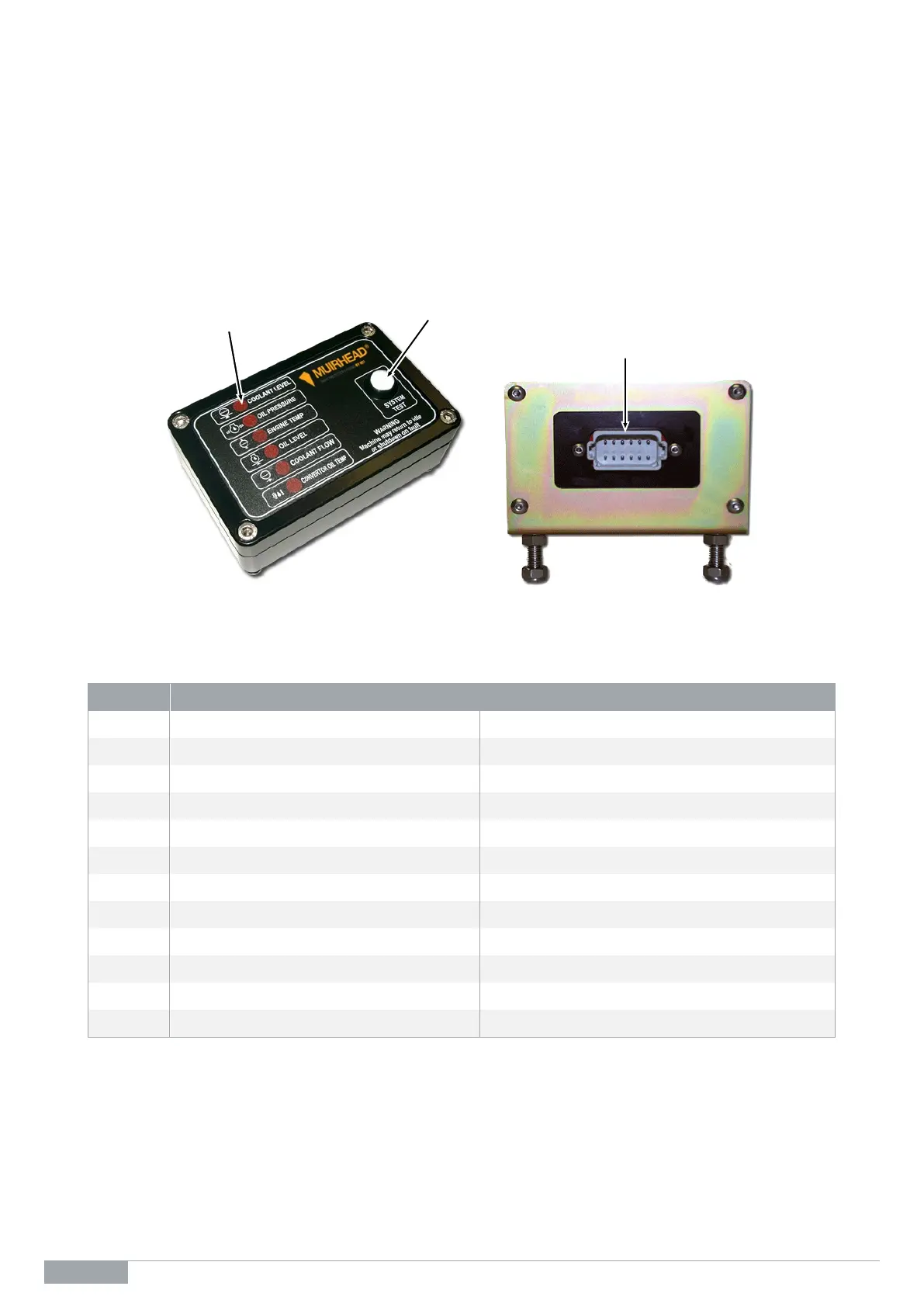
The EPS label displays the alert indicator or function that has faulted. A test switch on the front of the EPS
control unit allows the operator to simulate a fault and test the complete system.
A connector with 12 contacts on the rear of the EPS control unit facilitates the necessary wiring for the inputs
and outputs.
Figure 2 EPS control unit external view
Wiring Connections
No. Function Type
1 +8 Vdc to +32 Vdc Ignition supply
2 −0 Vdc ground Ground
3 Output 1 Alarm control
4 Output 2 Idle control
5 Output 3 Energised to run control (ETR)
6 Input Start input
7 Function 1 Ac circuit/switch input
8 Function 2 Switch input
9 Function 3 Switch input
10 Function 4 Switch input
11 Function 5 Switch input
12 Function 6 Ac circuit/switch input
Alert Indicators
12-pin Connector