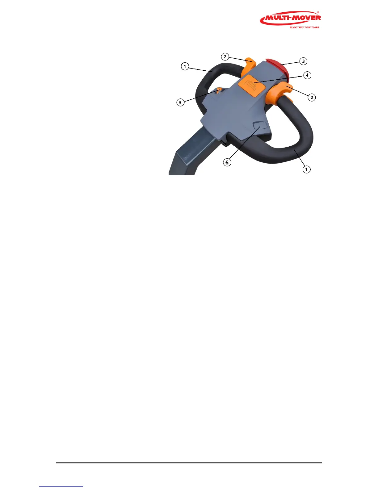
Steering handle (Tiller head) (fig. 2)
1 Handle black
2 Drive switch
3 Emergency stop (red)
4 Buzzer or optional # Horn
5 Step less speed control, Potentio Meter
6 # Hydraulic or electric hitch
Steering handles (1)
The steering handle (1) with bar is a fixed part of the Multi-Mover XL35, moving to the left means
driving to the left, and vice versa.
Safety switch (3) Belly Butto4
When pressing the safety switch (risk of getting jammed), the Multi-Mover XL35 will stop immediate-
ly.
In order to start again, the drive switch must first be placed in the neutral position.
# Coupling point upward (3), # coupling point downward (4)
Optionally, the coupling point can be moved upward/downward with an actuator (spindle motor).
This serves, for instance, to make it easier to move a tandem aXL35e trailer.
Signal switch (5) only upon request
Optionally, a horn can be connected to the signal switch Buzzer(5).
Drive switches (2), left and right from the centre
By rotating the drive switch (2) to the front with your thumb, the driving direction will first be
switched on and then, when rotated further, the Multi-Mover XL35 will start to drive. The central
position is the neutral position.
By rotating it downwards, the Multi-Mover XL35 will reverse.
Caution! Only switch to forward or reverse if the Multi-Mover XL35 is standing still.
Ignition lock (5)
The ignition lock (5 fig. 1) is used to switch off the batteries, aways switch off the battery in case of
maintenance to the Multi-Mover XL35.