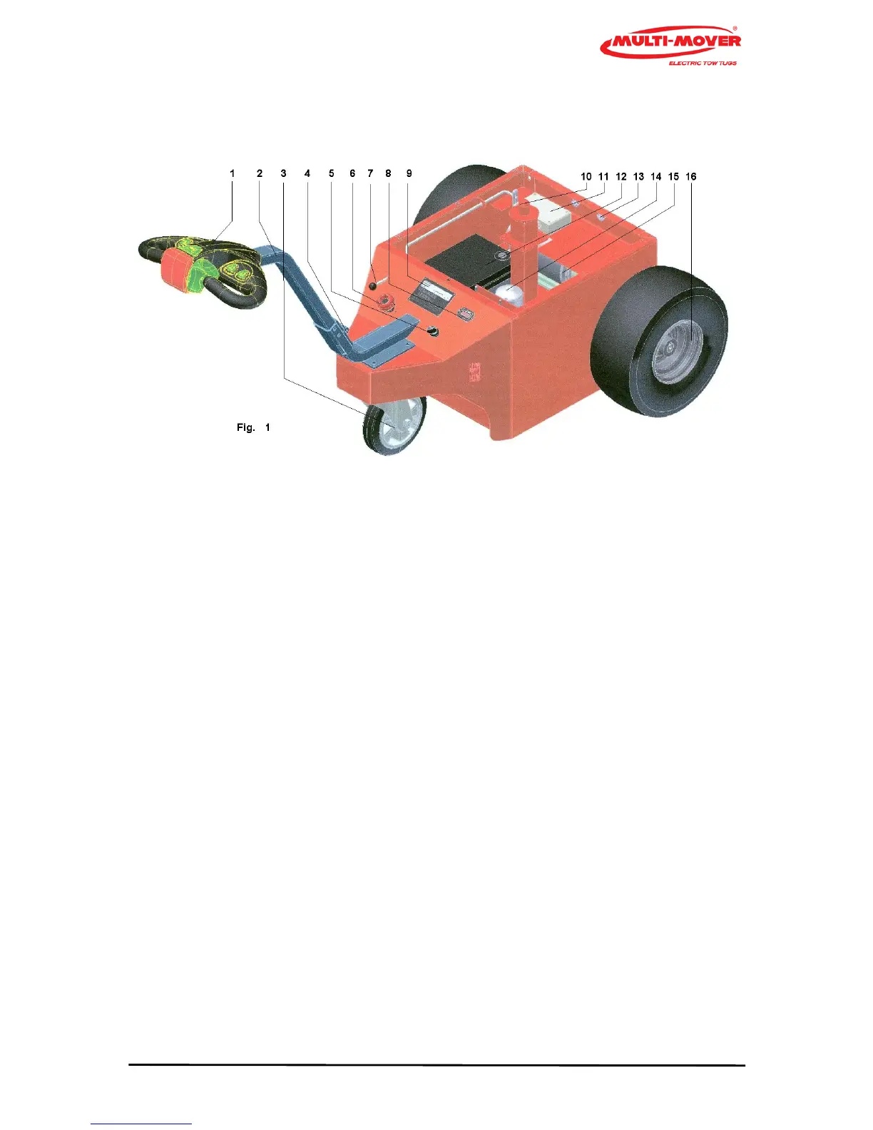
5.3 Operation (see photo, fig. 1)
1 Steering handle (Tillerhead)
2 Steering bar
3 Swivel wheel
4 Hinge point steering bar
5 Ignition lock
6 Emergency stop
7 Electric Magnetic brake release
8 Battery indicator
9 Type plate
10 Top coupling point
11 Control box
12 Battery
13 Connection point for tow pole/eye
14 # Actuator or Hydraulic hitch C
15 Motor with reduction gear unit
16 Wheel with tyre
Prior to putting the Multi-Mover XL35 into operation, you must acquaint yourself with its possibili-
ties. Read the instructions in advance and check the function of the control units with the ignition key
in the OFF position.
Electric Magnetic brake (7)
The wheels (16) are coupled to/disconnected from the motor (15) by means of the handbrake
button. If the button is pulled out it is in the free position, the Multi-Mover XL35 can now be freely
manoeuvred by hand.
If the button is pressed down, the Multi-Mover XL35 can only be driven electrically.
Optionally (#), the coupling point (10) can be moved approx. 20 cm upwards/downwards with an
integrated actuator or a hydraulichitch.