16
IHL_UDARA_2016_11_04_BEGB
4.2.6 Maximum length of the fl ue gas outlet
Warning!
The maximum allowed length of the fl ue gas outlet
must not be exceeded.
Depending on the used fl ue gas outlet and appliance
types, the maximum length of the fl ue gas outlet and
combustion air supply vary.
The maximum length is the sum of the following: the
length of the straight pipes (L, L1 + L2, or L1+L2+L3 in
the fi gures)/ the equivalent length of the other
elements such as bends or intake fi lters that you can
fi nd in the table below.
4.2.7 Allowed materials
Attention!
Never use fl ue gas outlet or combustion air supply
piping made of PVC. Do not use aluminium for the
fl ue gas outlet either.
You can use PP pipes as fl ue gas outlet pipes if local
standards allow this. If not, use gas-tight pipes made
of stainless steel of the 40, 50, 60 or 70 type in accor-
dance with the EN 1856-1 standard.
You can use PP pipes as combustion air supply pipes
if local standards allow this. If not, use gas-tight pipes
made of stainless steel of the 40, 50, 60 or 70 type in
accordance with the EN 1856-1 standard.
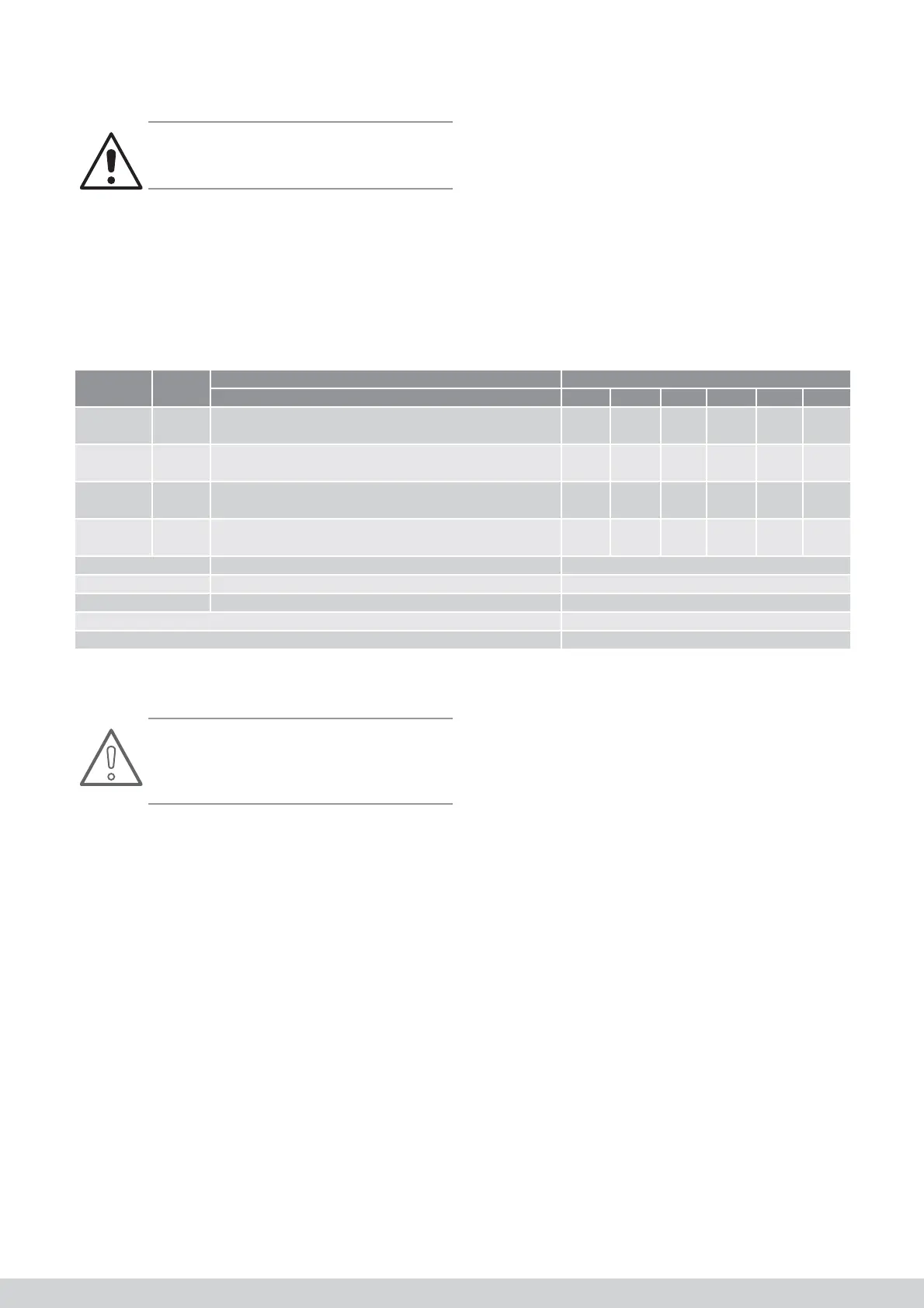
Table 2: Maximum allowed length of the fl ue gas outlet
Type Ø Remarks Maximum allowed length
Udara HR (DF) 10 15 20 30 40 50
B22P
C52
80 mm Smooth pipes in PP/RVS
Flexible pipes MG Flexline in the fl ue gas outlet
30 30 30 30 30 20
C12
C32
80/125
mm
Concentric systems with wall terminal
Concentric systems with roof terminal
12.5 12.5 12.5 12.5 12.5 10
C12
C32
80 + 80
mm
Parallell systems with wall terminal
Parallell systems with roof terminal
20 20 20 20 20 15
C92 80/125
mm
Concentric pipes dans la chaufferie
Flexible pipes MG Flexline in the fl ue gas outlet
12.5 12.5 12.5 12.5 12.5 10
Bend 90° Bend 90° 2.00
Bend 45° Bend 45° 1.00
Bend 30° Bend 30° 0.75
Intake fi lter 4.00
Protective vent 1.00
4.2.8 Position of the terminal
All applicable standards must be respected with regard
to wind attack and pollution. If local standards are not
available, use the following guidelines:
• Every terminal must be located in a square of 0.6
m without obstacles.
• The distance between a roof terminal and a
vertical wall must at least be 0.5 m.
• The distance between a roof terminal and a wall
that makes an angle with it and in which windows
can be found must at least be 2.5 m.
• The distance between 2 roof or wall terminals
must at least be 0.6 m.
• The terminals of 2 end pieces that are one on top
of the other in a wall must at least be 2.5 m
• Terminals may not be installed under a porch roof.
• The terminal must at least be at a distance of 1.0
m from the plot border.
• The wall terminal must at least be 1.0 m above
ground level and the roof terminal must at least be
0.4 m above the roof (in connection with snow).
• The wall terminal must at least be at a distance of
0.5 m from the corner of the building.