IHL_UDARA_2016_11_04_BEGB
29
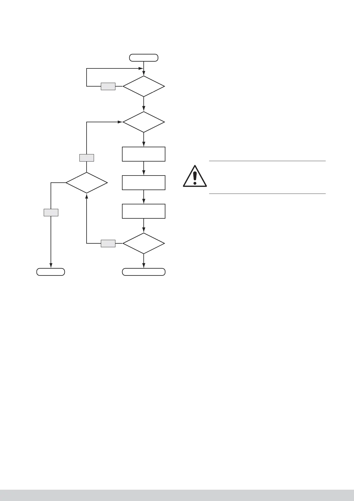
8.1.4 Ignition fl owchart
Start
Warmte-
vraag?
Zelftest
ok?
Voorspoelen
(t = variabel)
Ontsteking
Gasblok open
Teller
+1
Ionisatie?
Brander aanLOCKOUT
Teller
< 5?
Ja
Nee
Nee
Nee
8.2 Internal error
Most “internal” errors are caused by a short-circuit in
the cable loom or because of a faulty burner manage-
ment control system.
Check the wiring in accordance with the fl owchart and,
if required, replace the burner management control
system.
8.3 Overheating and NTC errors
1. Check the fi lter for dirt.
2. Check whether suffi cient air vents are open.
3. Check whether the ducts are suffi ciently large.
4. Check the operation of the system fan and the set
air fl ow rates. If required, increase the set air fl ow
rates or lower the power of the appliance by adjus-
ting parameter TSP 10 in the burner management
control system.
5. Ensure that the appliance can blow without
obstruction (especially with regard to downfl ow
appliances).
6. Check the operation of the temperature probes.
The resistance of the probes will be approximately
10 kOhm at room temperature.
7. Check whether the double NTC (discharge air tem-
perature) has not been exchanged with the single
NTC (intake temperature).
8. Check the settings of the temperature protection
by comparing the set parameters with the table in
the manual.
9. Check the cabling of the NTCs to the burner
management control system.
8.4 Display does not work
1. Check the power supply.
2. Check the connection of the control unit with the
display.
3. Check the fuses on the interface printed circuit
board system fan display.
4. Check the fl at cable between the interface printed
circuit board and the display.
Warning!
Pay attention to the correct connection of the fl at
cable. If you press this incorrectly into the connec-
tor, the display can be irreparably damaged.
8.5 Flue gas fan operates continuously or
not at all
Check the control cable (X23), if the PWM signal to
the fan has been interrupted, the fl ue gas fan runs
at high speed. If the control cable is OK, the burner
management control system or the fl ue gas fan will
probably be faulty.
If the fl ue gas fan is not working despite the heat
demand, check the cabling and check whether the
appliance is not locked. Measure the voltage that must
at least be 230 V ± 10%. Replace the fl ue gas fan or
burner management control system if required.
8.6 System fan operates continuously or
not at all
If the fan is operational continuously, check whether
the fan position is set to OFF. If this is not the case, it
is normal that the fan is operational.
If the fan is not operational despite the fact that a
percentage speed is being displayed on the display,
fi rst check the power supply voltage of the fan. If this is
OK, check whether the fan can turn freely.
8.7 No communication with thermostat
Check the cabling. This must, by preference, be a
shielded and twisted cable with a maximum length of
20 m for the RC21.
Yes
Yes
No
No
Ingnition
Injection gas
Ingnition ?
Burner ON
Compteur
< 5?
Teller
+ 1
Request
?
Succesfull
calibration ?
Rinse
t=variable