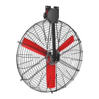
Galvanized Box Fan 130
10 | ENGLISH Original instructions INS00025-A
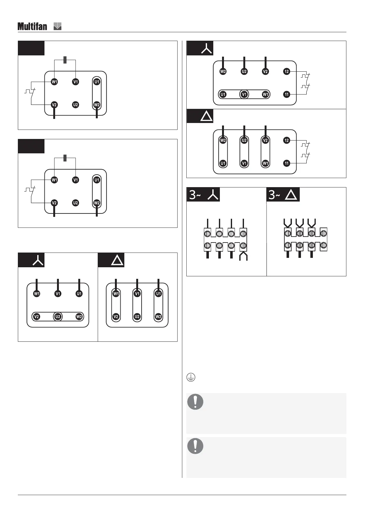
Illustration18: 1~
Illustration19: 1~ (North America)
For 3~ fans, depending on the motor model used in your fan either a terminal
block or a luster terminal is present.
L1 L2 L3
3~ 3~
L1 L2 L3
AB03 AB04
AB01 AB02
Illustration20: 3~ STAR / DELTA (standard terminal block)
3~
3~
AC
TB
TB
L1 L2 L3
TB
TB
L1 L2 L3
Illustration21: 3~STAR / DELTA with optional thermal detectors (thermostats)
yellow
ged
grey
brown
purple
blue
yellow
blue
red
grey
brown
pruple
AF01
AF02
L1 L2 L3
L1 L2 L3
Illustration22: 3~ STAR / DELTA – counterclockwise rotation
NOTICE! STAR is for HIGH voltage / DELTA is for LOW
voltage
Control
This fan is supplied without a control or control system. You can use a control
or a control system for operation of the fan.
Isolator
This fan is supplied without an electrical isolator (supply disconnecting
(isolating) device). An electrical isolator must be provided to facilitate safe
maintenance and troubleshooting.
Grounding
The fan must be grounded. Ground the fan according to local
regulations.
NOTICE
Overcurrent protection
The use of an individual separate overcurrent protective device per
fan is highly recommended.
NOTICE
Overload protection
The use of an individual separate overload protective device (Motor
Protective Circuit Breaker) per fan is highly recommended.