9
Assembly instructions
Before assembly
Use the list of components on page 8 and
Fig. 01
+
02
to check the
completeness of the components supplied.
We recommend using a soft, clean and at surface to ensure the model is
not damaged during assembly. Always use, unless otherwise specically
stated Zacki ELAPOR
®
CA instant adhesive to glue the model.
1. Assembling the elevator
Slide the elevator
7
into the rear of the fuselage
4
and check the
t and that it is at a right angle to the fuselage. Pull it back out again
from the rear and sand the contact surfaces slightly to ensure the
adhesive adheres better later on. Make sure it ts correctly again. If you
are satised, apply Zacki ELAPOR
®
to the fuselage and then insert the
elevator
Fig. 03
. If necessary,
use a paper towel to remove any excess
adhesive. Ensure that it is at a right angle to the fuselage and that the
lengths A and B
are identical
Fig. 04 + 05
. A little activator spray speeds
up the process.
Use the remote control to set the elevator servo to the neutral position.
Make sure the elevator ap is also in the neutral position and screw the
pushrod to the elevator horn.
2. Assembling the rudder
Proceed with the rudder in the same way as with the elevator. This means,
initially
check correct t, then sand accordingly, apply adhesive, and align
Fig. 06
.
Ensure that it is also at a right angle to the fuselage
Fig. 07
.
Use the remote control to set the rudder servo to the neutral position.
Make sure the rudder ap is also in the neutral position and screw the
pushrod to the rudder horn.
3. Assembling the undercarriage
Screw the undercarriage
⓰
to the fuselage using the self-tapping
screws
⓱
Fig. 08
.
4. Assembling the wings to the fuselage
The long CFRP tube
⓬
is the rear main spar and the short CFRP tube
⓭
is the front auxiliary spar. Slide the spars into one wing and insert it
into the fuselage. Now slide on the other wing and make sure that both
servo cables are routed upward into the fuselage
Fig. 09
. To secure the
wings, insert the wing lock
⓮
from above into the slots of the two wings
Fig. 10
.
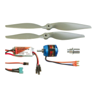
5. Assembling the propeller
Push the propeller coupling
⓳
as far as possible onto the motor shaft.
Balance the propeller
⓲
, e.g. using the propeller balancer # 33 2355
or similar. Slide on the propeller and then the holder for the spinner
⓾
.
Slide on the washer and screw on the nut
Fig. 11
. Tighten the nut rmly.
Finally, position the spinner
⓫
on the holder.
6. Assembling the receiver
Insert the servo plugs into the receiver and use the hook and loop tape
⓴
and
㉑
to x it to the area provided for this purpose in the fuselage
Fig. 12
. The servo plugs are labeled as follows:
1 LH aileron; 2 Elevator; 3 Rudder; 4 Motor; 5 RH aileron
7. Assembling the battery
Use the hook and loop tape
⓴
and
㉑
to x the battery to the battery
board
Fig. 15
and tighten the hook and loop strap
㉒
around both
Fig. 13
. Insert the battery into the battery rail
Fig. 14
and also x it into
position using the hook and loop tape
⓴
and
㉑
, as well as a hook and
loop strap
㉒
. To do so, thread the hook and loop strap through the slot
in the battery board and in the Elapor and tighten rmly
Fig. 15
.
8. Preflight check and center of gravity
Always check the model before ying it for the rst time. Check the
following points before the initial ight:
• Rudder horns tight
• Servo screws tight (cross-head screws)
• Linkage rod tight (hex grub screws)
• Make sure the spinner is running true by rotating the propeller by hand
Position and secure the battery (3S 2600 mAh 40C) and the receiver in
the model using the hook and loop tape and strap so that the center of
gravity at the fuselage is 110 mm behind the leading edge
Fig. 16
.
9. Rudder deflections
10. Initial flight
Carry out a range test and make sure all the rudders are running in the
correct direction and are in the neutral position. Start the model from
the ground and familiarize yourself with the ight characteristics at high
altitude.
Normal settings
Aileron distances
40% Expo
Mounting points
Aileron +/- 30 mm
Innermost servo Outside rudder horn
Elevator +/- 40 mm
Innermost servo Outside rudder horn
Rudder +/- 55 mm
Innermost servo Outside rudder horn
3D settings
Aileron distances
60% Expo
Mounting points
Aileron +/- 50 mm Servo 2nd hole from
outside
Outside rudder horn
Elevator +/- 60 mm Outermost servo
Center rudder horn
Rudder +/- 85 mm Outermost servo
Center rudder horn
EN
 Loading...