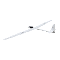
DG
600
building
instructions
Dear
modeller'
"tt/";"'i;;;ü
i'"t
purchasins a
MULTIPLEX
model
kit
, . -,.-
i'liüirräL?iiii"
,itderso
a
säries
oI
material
and
qualitv
ch€cKs'
ä;;
;;;;;;;; vou
iitt
be
satisfied
with
the
contents
or
vour
iii.
il;;;;;t,;;
i'ould
ask
vou
to check
allthe
kit
componenls
;l;i;i-"i;öthil,
as
it
is nöt
possible to
exchanse
parts
which
are
no
longer
in new
condltlon'
We
hooe
you
enjoy
building
your
model'
and
gain much
plea-
ÄLi"
tät'opetaiing
it
once
it is
complete'
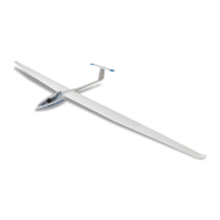
Specification:
winqsoan:
3500/3160
mm
Fusölage
length:
1455
mm
Winq
area:
57
/ 54
dm'
All
rip
weight:
ca.
29009
Wins
loading:
47
I 49I
I dm'
Wing
section:
Ritz
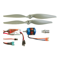
RC
functions:
Ailerons
(optional 1 or
2
servos)
Elevator
-,dder
.-,7brakes
ODtional
aero
-
tow
couPllng
There
are
three
possible methods
of
operating
the
aileronsone
servo
in the
fuselage;
Two servos
in
the
fuselage;
Two
servos
in
the
wings.
Two
aileron
servos
give
you
the.option
of electronic
aileron
dif-
ieiJniia-r
äs
*"rr
us
t:he
possibilitv of
using
the
ailerons
as
cam-
läi-
cnanging
flaps
(these
facilities
must
be
provided bv
your
transmitter).
Note:
lt is
essential
that
you
do
not
use
solvent
-
based
adhe-
$;;
;ffä;ilö
wood
to-stvrofoam
lnstant
slues
(cvano--
ää*i"iäiltdn
aiZap
and
zacki
arc
particularlv destructive'
Üie
s-minute
epoxy
or
white
glue
The
control
surface
horns
28
are
used
as
follows:
1 bored
1.3
mm
for
rudder
2 bored
1.7
mm
tor
ailerons
'1
bored
1.6
mm
tor
elevator
..*r{e
fuselage
fne
tirst
stag-e
is
to saw
out
the
cabin
lrame
and
instrument
bin-
"äää
ö'Jtö
the
line
marked
on
the
underside'
and
clean
up
iiäl"i
ääl"""
cneck
that
it-flts.
snuglv
on
the
fuselage
' ..^
iü"iäsäi;,iin"
""rvo
plate.13 should
be
bevelled-!o
matcn
Ine
curvä[,iä
ot
tne
ruselage
The
outline
of
MULTIPLEX
Nano
and
ü]"rä'"ervos
is
oie
-
stamped
into
the
servo
plate lf
you
intend
;äiü;iri;;;;i";tos,
alier
the
aoertures
to
suit
The servo
plate
also
tnctuoes
an
aperture
for
the
On/Off
switch'
The
elevator
and
rudder
servos
are
mounted
on
their
side
on
rne
;"":""
jfj"rt
1".
for
this
(risht-angle
brackets
or
quick-rel-
;:11
ff
:lilLt.rlH:it
*;n,:?"
3
il
X f
""
TT-
i 3TSl"1
the
screws
15.
il;;;rv"
plate
is
now
{itted
horizonlally
in
the
fuselase
wltiJ:
;ii;;;:
'PiJ";'th;
;äbin
fr.ate.
on
the
model
to check-that
rne
öiuiä
Jo"i
not
push
the
fuselage
out
of
shape
The.
fuselage
äiärlil:,""r;i;*lal"tl""f
gnglTel1ilJ":,.Föh''^'.ql
itli::;"*"t*trili::*s.';:"'""":lllfl
i'"13[,i1""ü?,"dlf
;
3?'JBi'Y,*,n",,n"i::T-LTiil1.:'ti3".?",.13t?,t;",.,"0"
Rouqhen
uP
the
fuselage
sroes
ljä""ä.
äiiii
ö;rt
l3 in-place,
usins.slow
-
settins
epoxv
(unu
äi"i-,jnaiä"i
ioo,
Multipoxv
or
Araldite)'
Glue
the
two
transverse
struts
11
toqether
with
their
edges
ää.
äJ;td;i";
has
sit,
bevelthe;nds
to
match
the
fusel-
äää äurvritut"
"tit'e
rear
of
the
wing
root
fairings'
check
that
the
sirut
fits
accuratelv,
and
glue
"
'nn:'i;f"n
,n"
,outding
out
of
Caution:
heck
that
the
strut
does
il,u,on?
no'""
and
aperturesrequired
in
the
wing
root.fairings
$ru.f"qäi"Aü]*T,':ffi
i#t"fr1'ä#:.r,'.vli,'i
äüir"Ji"iii"tti,
then
f
ired
"*,11i:if,3
$lil?iljlTin-"nn
The
slot
for the
wing
joiner
only
n
ir'äri'"ärää.j*ärr,
,iiÄg
a 2
mm
Oritt
as a
millins
cutter'.Leave
on-
il.ilFJJT"'J:i'fiik:':ä1111i13'ü:T"'lii:'x"":i'il:
slot
as
a
guide.
Wing
ioiner
assembly
Ä"""är"
ti'"
two
rectangular
brass
tubes
50
as-
shown
in
the
äi"rii""ö,
äiäirip
ttte
two
side
cheeks
onto
them
ch€ckthatthe
t"ü;;;"
the
right
wav
round
-
rioht-hand
blade
to
the
rronl'
.":ru:"^,;!il;i:lr,l*t"'s$?:tl"ü'iä:{i{i:1li
ätäri
r oäÄ-it'b.t
of
the
opposite
fuselage
side
-The-wins
dF
tääiäri"
o"i"ttined
bv
the.spacins
of
the
side
"he."Ki;
-.^
i.äläätou"
t"it
trights
häve
shown
that
a
dihedral
angle
or
/ oe-
l*el:l$;r'l*Jll*;:::u'lr?"l1,;;ü11llY:l*ir;
the
dihedral
from
this
figure'
{Dihedral
:
3.5
degrees
per
wlng
Total
dihedral
=
7degrees)'
b"taäin;
,";i;;s"iar
bräss
tube-s
on
the
ansle
iis
and
shift
th-e
!iää""ü!äi".-r"iiittt"
dihedral
is correct
The
two
cheeks-
must
#::,il-ffi81.'i'"#[ff
Tl'"":g'l'?"i;"""Jisfr?':lilli?I:
cheeks
on
the
brass
tubing'
Ä.iäÄor"in"
ioi"er
clamp
äs
shown
in the
drawing
Besureto
iit-t"riä
"äödäi
ti""t
in
the
clamp
backplate;
it
is
a
good idea
to se-
V:'f
J:xl:"""L'.?
";tii:"J-"il:S";;
"'en
-
head
machine
screw
as
the
clamp
screw;
both
are
supplied'
Caution:
Never
tighten
the
clamping
screw
unless
both
wing
ü-i;;;ä;;;;t"
i^
place
in
the
tube!'
otherwise
the.tubes
will
lä
"ii.iälnää'
""0
tire
joiner
blades
will
no
lonser
rit
iiÄTiäiijJääö"
"lots
i{
necessary
to
ensure
that
the
joiner
as-
sämuiy
is
a snug
f it, but
do
not
9llinvo"ttn"
*ing
ioiner
tube
as-
The
next
stage
-
adjusting
and
lnsr
;"*itt[*i;;l+n;:''";'::::'un:ir*J*^""""$t"{::
;ffiii;
;G
roiner
oraoes
50
and
the
locatins
pins
48
in
the
;i;äs'i;"'
;;i
öi;"i.
Fit
the
joine'
as"emblv
in the
ruselase'.ano
;ü;i;iü;t"ö;.
öheck
thät
the
winss
line
up
with
the
root
tar-
liüä'l'tiä'tlit
öä"i
the
apertures
in
ihe
fairinss
untilalisnment
;i'öäjl;.ilü;otrv
u'oout
anv
gaps; thev
will
be
rille-d
later'
ötrect
ttrat
the
wing
joiner
components
are
aligned
S99EdI,g
i" t"näi.äü",
ä"0
sl'uä
the
side
cheeks
to
the
tubes
using
5
-
mr-
lii?"l,ir"frl
.rnnen
up
the.inside
or
the
ruselase
SlqTg^l!:
i;;;;:i"iÄ,
anispot-gtue
th€
ioiner
assemblv
in
place.usrng
i"- äi^i,iää'oä,.v t.io
noiglue
the
assemblv
permanentlv)
Leave
ihe
glue
to
set
for
about
fitteen
mlnules'
öu'r""tr.,ttv
,"tou"
the
wing
panels and
joiner
blades
Apply-tape
iJit'"
ä'uilio"
of
the
fuselage.over
the
wing
root
fairings
lne
uiinäloin",
""."tbly
can
now
be
permanently
bonded
into
the
äj!ääää."'ulä
iiä-'J-sätting
epo:tv
ror
this'
thickened.with
"i-o-öiää
gi""" rouings,
micro
-.balloons
or similar'-The.best
m-e-
it
ääüiä
iuotr.
on
onä
side
at
a.time,
and
leav€
the
luselage
resl-
i""'än-r'n.t siOe
untilthe
resin
has
cured
This
prevents any
rlsK
äitiä
iJli"
s"1ti"n.'
^p,L".yiry,,i'ir";
3i3"Iil1;
brass
tube
Be sure
to
aPPIY
Plenty
ol
resln
ir-niin
äo".
nötidactr
io
the
fuselageksidS'
enos
ot
the
joiner
When
the
resin
has
cured'
sanr
i"üäiriüih
*itn
*'ä
fuselage
root
fairings'Take
care
not
todam-
age
the
fuselage!
'15
 Loading...