
M
mcdanielkathrynAug 20, 2025
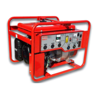
Why does my MULTIQUIP GA6HR overheat?
- CCody MurilloAug 20, 2025
If your MULTIQUIP Portable Generator engine overheats, several factors could be the cause. It might be due to the wrong type of spark plug, so consider replacing it with the correct one. Another possibility is using the wrong type of fuel, which should also be replaced. Check if the cooling fins are dirty and clean them if necessary. Ensure that the intake air is not restricted by dirt or debris, and replace the air cleaner elements if needed. Lastly, verify that the oil level is at the proper level, adjusting if it's too low or too high.