SETTING UP AND CONFIGURING THE DEVICE
20 Conduit
®
Cat 4 for North America MTCDT-L4N1 Hardware Guide
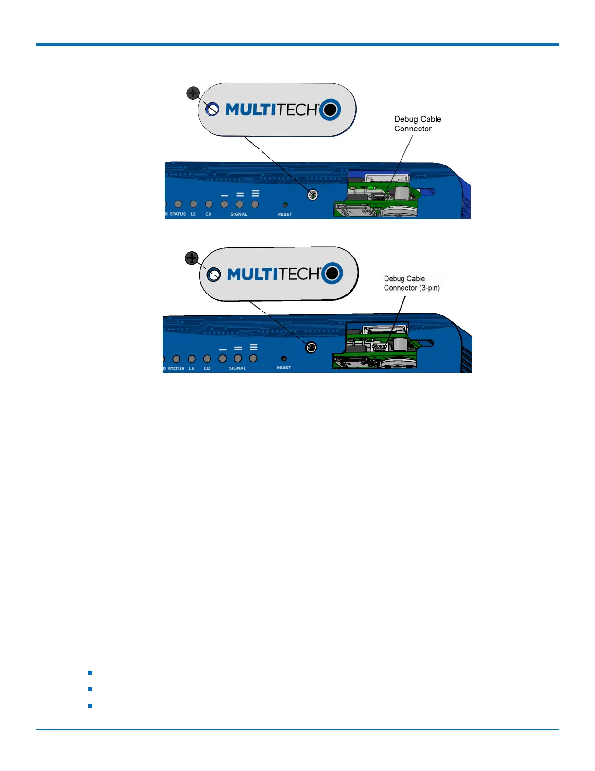
b. If you have the 3-pin connector, connect the 3-pin cable to the debug connector.
5. Connect the Type A end of the USB cable to the host.
6. From the host, use an application such as TeraTerm with a baud rate of 115,200. If the USB driver does
not automatically install, do the following:
a. Unplug the USB cable.
b. Go to the following web site to download and install the appropriate USB driver:
https://www.maxlinear.com/support/design-tools/software-drivers
c. Plug the USB cable back into the housing.
7. From the host, access the Conduit's USB COM port.
Accessory 3-pin Cable for Debug Interface
The 3-pin Debug Interface cable can be ordered as an accessory from the factory, P/N: 95218134LF, model: CA-
MTCDT-DEBUG. Otherwise, you have the option to build it yourself. See details in the following section.
Building the 3-pin Cable
As an alternative to the accessory cable for the 3-pin debug connector, you can build a custom cable to use the
debug interface. The resulting cable should have a USB-A connector for the host end and the 3-pin connector on
the device end. See tables under the cable and connector information for specific parts and manufacturers that
you can use.
You need:
USB to 3.3V Serial UART cable
JST-ZHR-3 connector (3-pin connector with crimp-style contacts )
Custom crimping tool (for use with JST connector only)