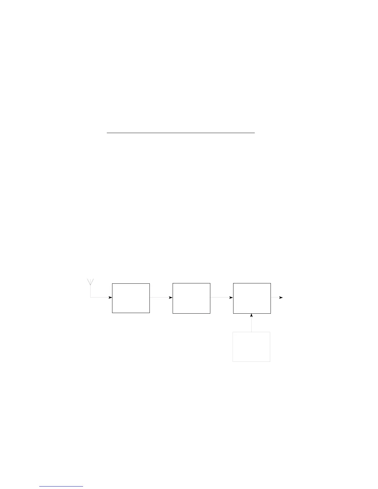
RF SIGNAL FROM
ANTENNA ON MAIN
BOARD
IF SIGNAL TO
MAIN BOARD
LOCAL
OSCILLATOR
XL301,TR304
MIXER
TR303
RF
AMPLIFIER
TR301,302
SAW
FILTER
FL301
PSG/10441/1
RPR 550IS Series
Page 3 - 8 TM1188 Issue 1
Figure 6: RPR 553IS Radio Board (Front End) Functional Block Diagram
Local Oscillator
19. Transistor TR203 and associated components form the third overtone Colpitts crystal
oscillator, with XL201 being the resonant quartz element. The oscillator is trimmed to
the correct frequency by C209. The collector of TR203 is tuned to the third harmonic
of the oscillator by L204 and C212. The local oscillator output, 455kHz above the RF
input, is fed to the mixer via C215.
The frequency of the crystal is calculated by the following formula:
Crystal (XL201) frequency (MHz) =
Receiver channel frequency (MHz) + 0.455MHz
3
Mixer
20. The RF and local oscillator frequencies are fed to the base of mixer TR204 to produce
an IF difference frequency of 455kHz across R209. The IF signal is fed, via SK201 pin
3, to the main board.
RPR 553IS RADIO BOARD (FRONT END)
21. Figure 6 shows the functional block diagram of the radio board (front end).
Antenna
22. The incoming RF signal is detected by the loop antenna AE1 which is fixed to both the
radio PCB and the main board. Coupling capacitor C48, on the main board, helps to
enhance the receiver performance. The antenna is tuned by C327, and the resulting
signal is fed to the RF amplifier.